Fuel System Changes
February, 2006 - All of this modification really started with my desire for cooler engine temperatures. "So what does the fuel system have to do with that?" you may ask. Other than my fuel injection unit being in the way of my air intake, nothing. But I had a plan to remount the fuel injection and one thing led to another and well...
First off, my fuel injection unit has performed pretty well in its current configuration. But it lays right in the middle of my air intake scoop/NACA duct and I figure that its blocking a lot of cooling air. I did a little "eye-balling" of the unit and determined that if I could turn it upside down It would clean up the lower part of the cowl nicely and let the air in without as much interference. In order to rotate the unit 180 degrees I would need to drop the intake elbow about 1-1/2 inches so that the fuel metering mechanism could clear the engine oil sump. Airflow Performance built be a nice phenolic adapter to drop the elbow, so I installed the adapter and turned the fuel injection unit 180 degrees.


With the unit down rotated from its previous location, I had to re-route the throttle and mixture cables. Unfortunately, the new locations put them right where the electric fuel pump was located on the firewall. Well, I never had liked the pump on the firewall, so I decided to move it. I chose the inside of the firewall in the lower gear well area for its new location, but that was where the fuel filter was located. OK, I never liked that there either because it was difficult to check the filter. Now is the time to move it too, so I decided to locate it in the rear armrest.
With all the decisions made on where the new locations for everything where, I unbolted the pump and filter and started remounting them. The filter needed to have the fuel line running from the fuel selector to the firewall cut and fitting attached, so that was the first job. After installation it looks like this.

Next I attached the pump to the inside firewall and plumbed new tubing to the firewall bulkhead fitting. This was a tight fit, but I shouldn't have to do much with it once its installed, so the remote location is OK.

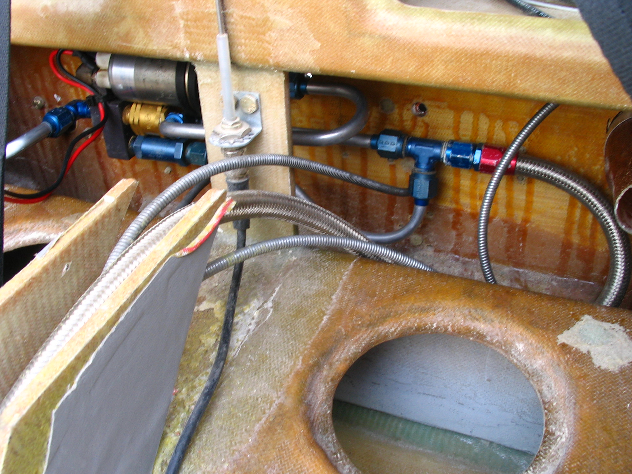
I could now run the throttle and mixture cables through the firewall in their new locations. I re-oriented the throttle and mixture arms to get the correct actuation and then made a bracket to secure the cables as they came through the firewall.
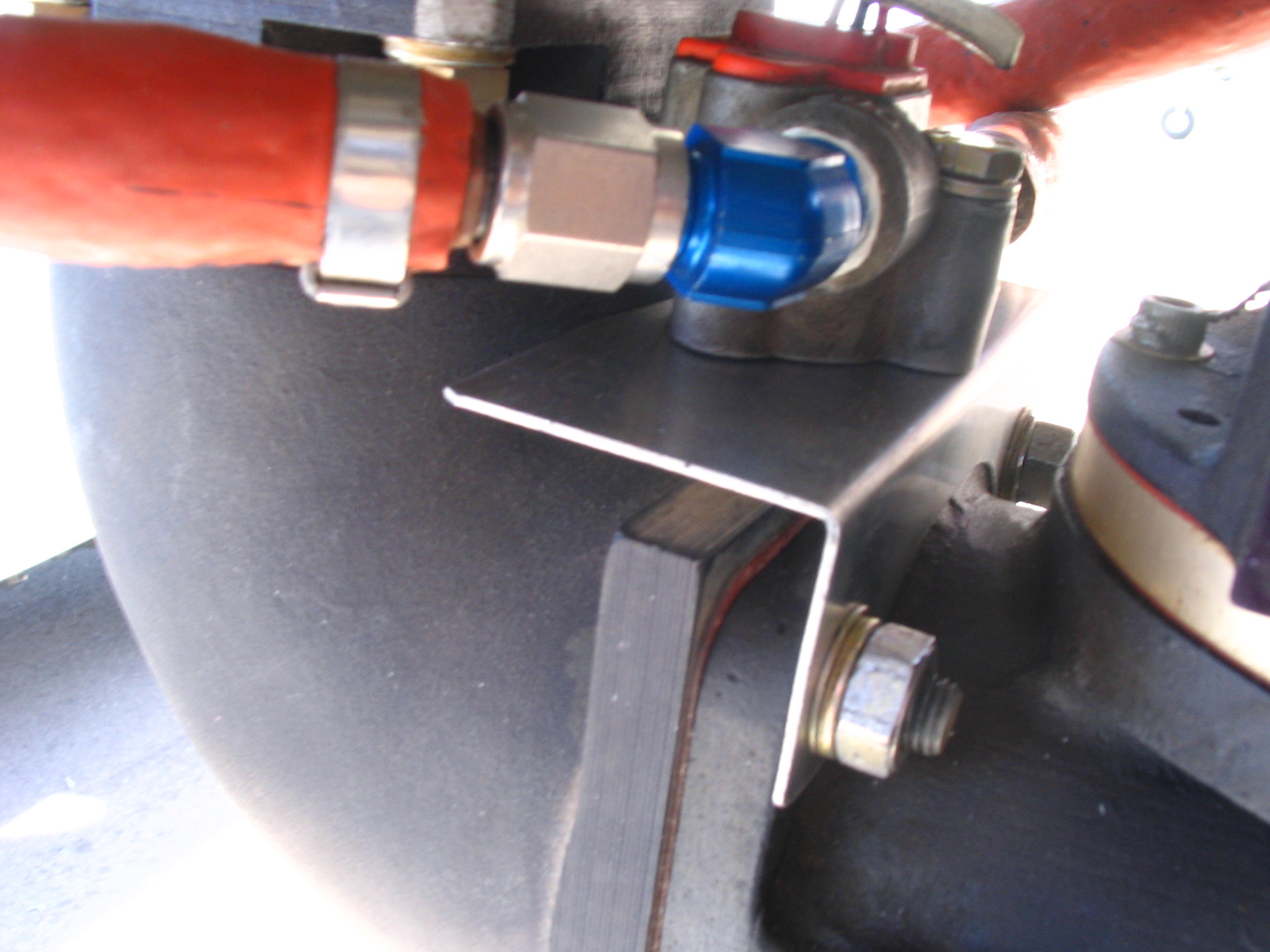
The fuel line attachments from the firewall bulkhead to the engine fuel pump where pretty straightforward. Without the pump in the way the firewall looks much simpler. From the engine driven fuel pump to the fuel controller I connected a short hose. I installed a bracket to support the fuel flow meter to the air intake elbow and then ran a hose from the controller to the fuel flow meter. From the fuel flow meter to the new flow divider I attached another hose. Here is the fuel flow meter and bracket mounted to the elbow.
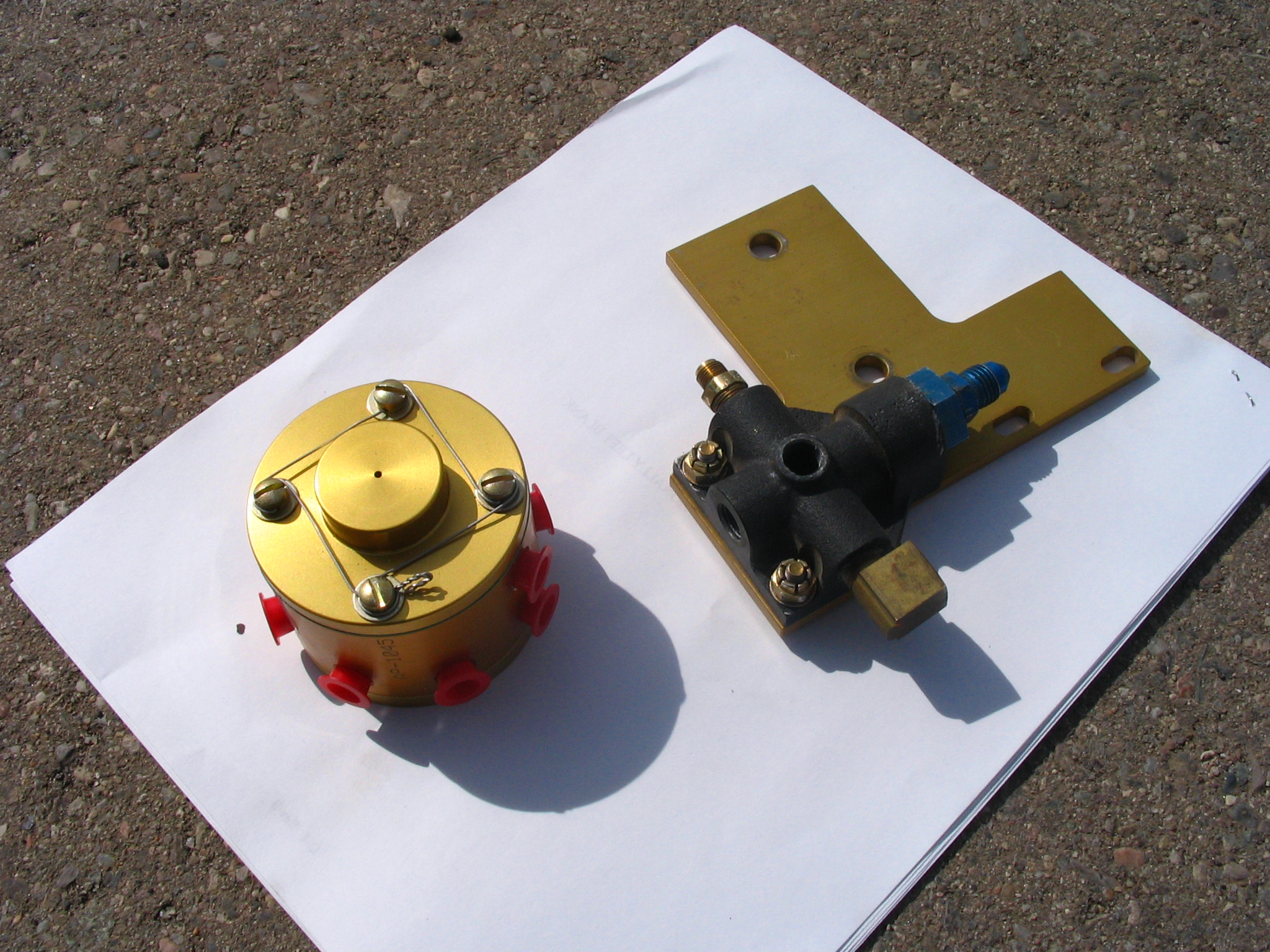
My Lycoming engine runs great at high RPM's but can stumble and spurt at low RPM's. In investigating this I came upon an interesting discovery on James Redmon's Berkut site. He had similar issues at low RPM and found that by replacing the fuel distribution block with a flow divider solved his problem and he can now run at smooth idle as low as 700-750 RPM. I called the good folks at Airflow Performance and discussed this with them and while they say the distribution block should normally be fine, the flow divider is more precise at separating the flow of fuel to the individual nozzle lines and could be retrofit fairly easily. I ordered the flow divider and then went about figuring where to mount it. Here is a picture of the old distribution block (right) still attached to it's mounting plate and the new flow divider (left).
The rear of the oil sump looked like the best location to mount a bracket and still be able to connect the fuel lines than I had with the previous arrangement. I test fit a paper template of the bracket and then attached the permanent one.
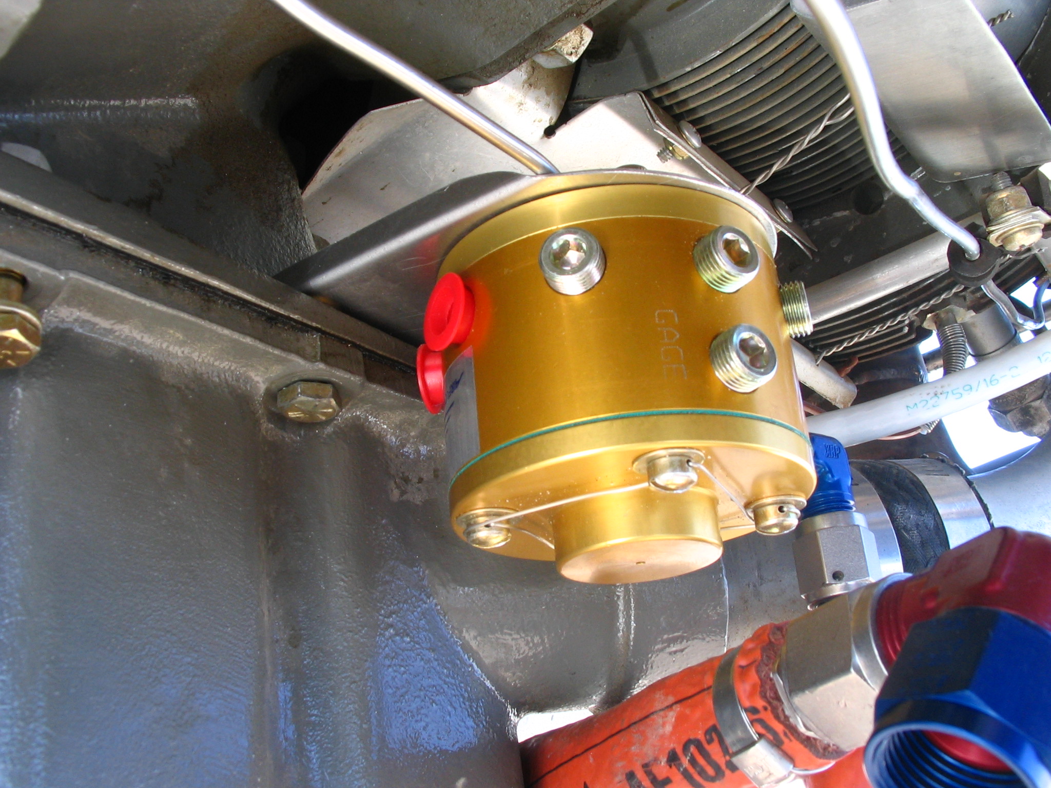
After removing the fuel lines and rearranging them to get the right lengths for the new location, I attached each end to the flow divider. Finally, the fuel system modification is complete! Here's a pictures of the final result.

And another one showing the installation with the oil cooler mounted - a little crowded, but it works!

Last Updated on July 12, 2008