In Cowl Exhaust Pipes
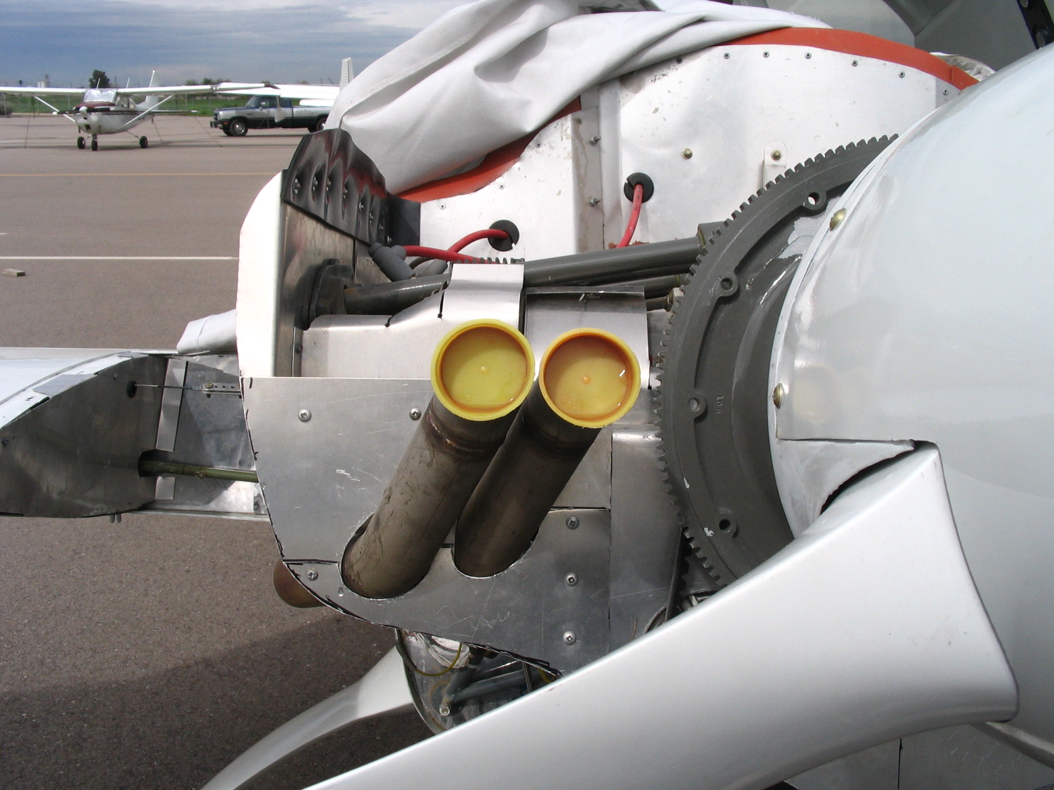
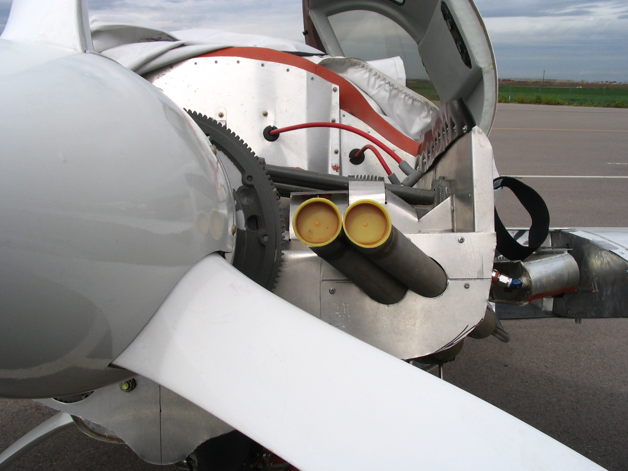
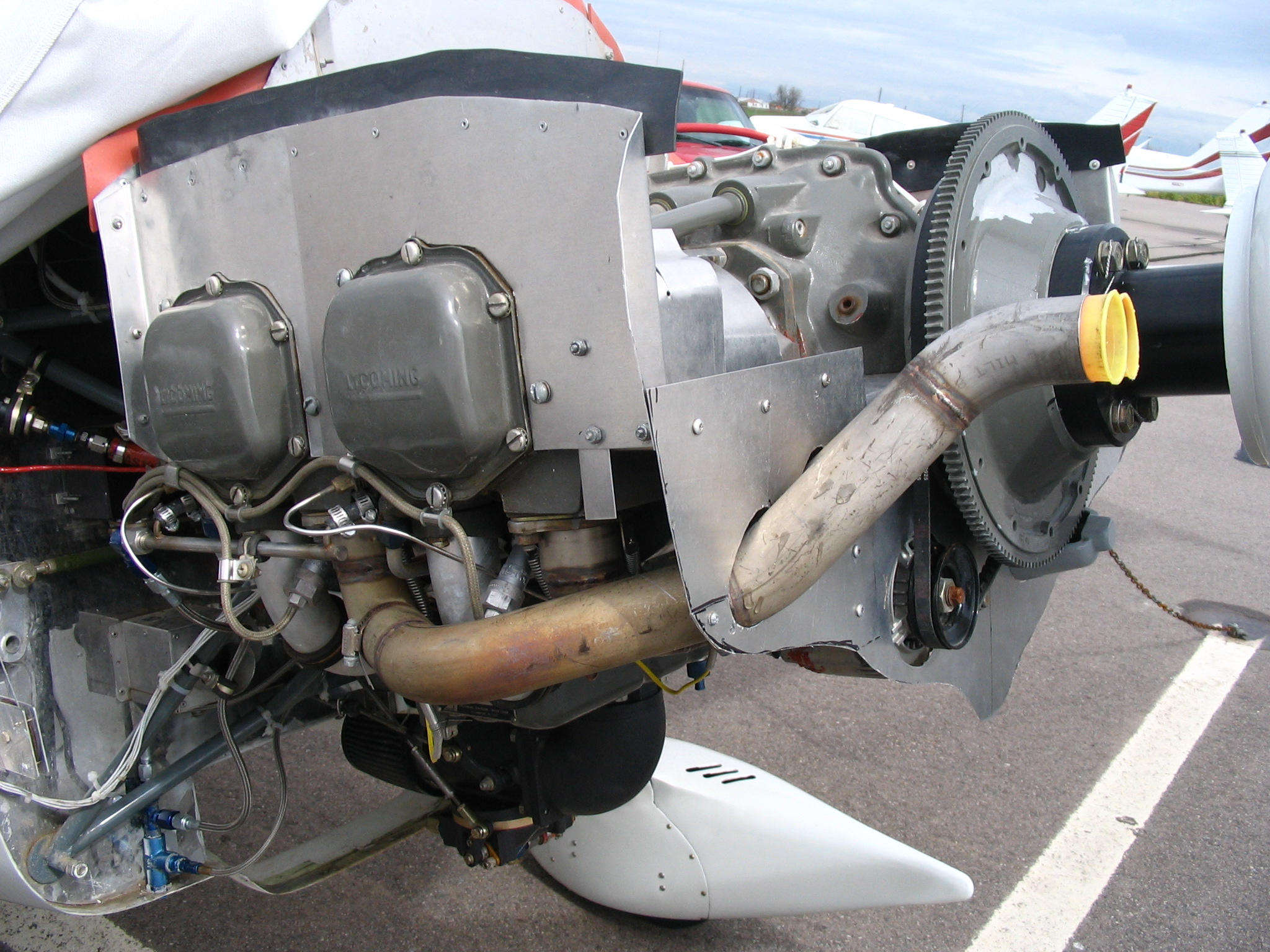
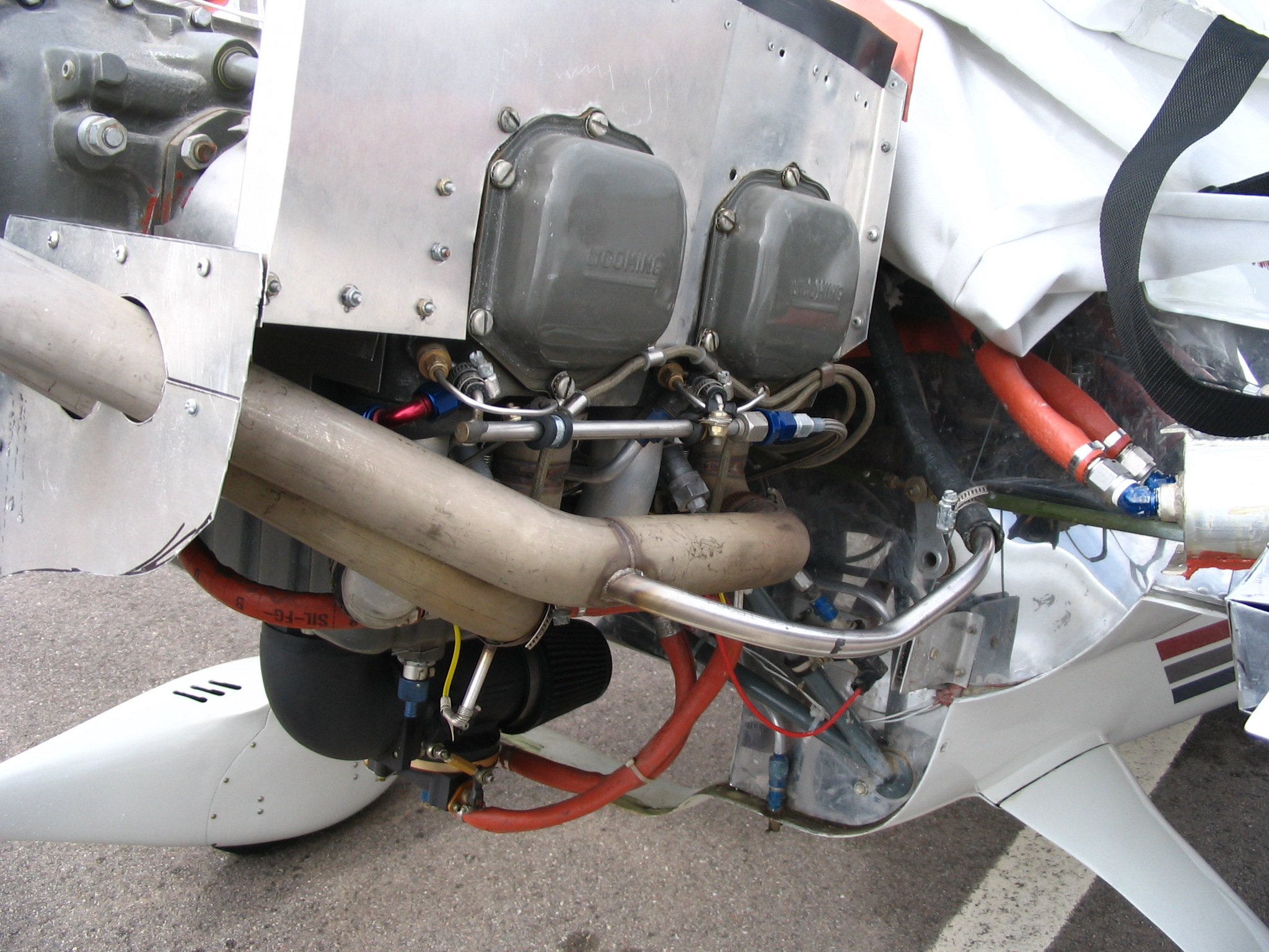
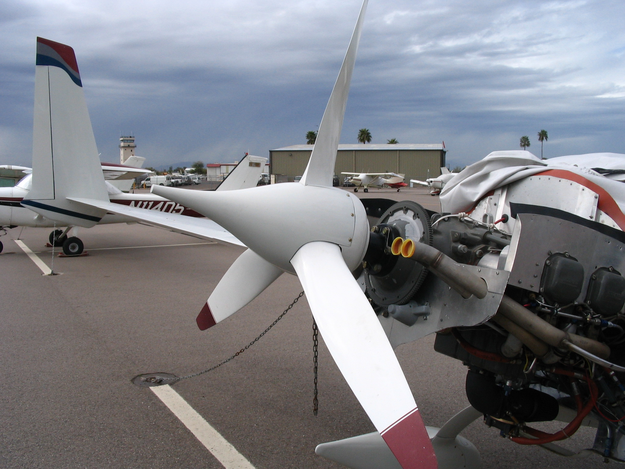
Dec '04 - April '05 - I purchased a set of in-cowl exhaust pipes in the summer of 2004 in hopes of installing them prior to my cross country flight later that summer. I had too many things to get done so I put it off until now. I started disassembling the engine compartment in December to fit the new pipes. They required a change to the baffling since they exit the cowls inside the exit air opening. I would no longer need the exhaust "bumps" in the existing cowl so I took the cowls home to hack away at them. The new pipes exit about 8 inches left and right of the prop centerline and fitting them was no problem. I had to make a few paper patterns of the baffling where the pipes go through them, and was surprised to learn that they went through at an angle instead of perpendicular to the baffles. That meant making the shape of the holes more like ovals. Once I figured out how I was going to make the pieces it was a matter of a few days of metal cutting and bending to get the baffles fabricated. After getting the baffles like I wanted, I took one of the pipes to my friend Tom McNealy who welded a stainless pipe into it for my air breather line to dump into. You can see it in a couple of the pictures below.
While I had the cowls off I thought I would look into re-orienting the fuel injection unit. It points toward the NACA scoop opening now and obstructs quite a bit of airflow. I disassembled the unit from the engine sump and rotated it 180 degrees so that the inlet now points toward the rear of the plane (toward the prop). Lots of room in that area, but the cowl will probably interfere and would need to reshaping. While I had the unit off something caught my eye. I have a white metal plate that is used as a throttle/mixture cable bracket that fits between the fuel injection unit and the engine sump. It has a hole in it that allows the intake air to pass thru it and what caught my eye was a gasket that was around the hole. The gasket was much larger than the opening of the hole by 1/8 inch all around. I thought - "could this be restricting airflow into my engine?". So I made some measurements of the sump opening and the plate opening and sure enough the plate opening was a smaller diameter than the sump. I then measured the fuel injection opening an it was the same size as the sump. I had essentially been running my engine with a restrictor plate! Doing some rough calculations, I determined I was restricting the opening to 80% of the design opening size. Now lights are going on in my head like flashbulbs! No wonder the engine isn't producing full power, no wonder the prop isn't turning at the RPM's it should, no wonder my throttle lever is useless beyond about 3/4 full! So, I kick myself for not seeing that much sooner and regretted sending my prop back to Craig Catto to be repitched. I've probably lost a few knots top speed due to the prop change. But on the positive side of things I should have much improved takeoff and climb performance! Here's a picture of the plate that was the culprit. The restriction was where the elbow attaches to the sump.
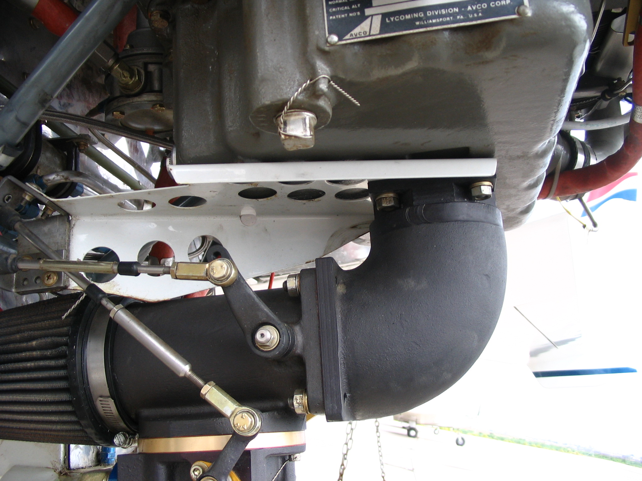
So, for the time being I decided not to do anything with the fuel injection unit in order to measure the performance pickup I get by opening up the hole in the plate to full size.
Back to the exhausts - with the baffles cut and the fuel injection unit back on, I went to work on the cowl modifications. I started by cutting off the bumps on both the top and bottom cowls. I made some cardboard templates covered with duct tape and taped them to the cowls in order to have a backdrop to fiberglass the new shape. I laid up 3 plies of BID over the templates and allowed it to cure. I'll focus on the top cowl first since it requires a bit more glass work. After trimming the glass to the final shape I sanded the glass then mixed up some micro for filler. I applied this to the glass and sanded it to get the final contour correct. I'll probably fly this a few hours before painting to give the glass a chance to cure better and make sure everything is right!
I took the cowls to the plane and attached them to make sure no interference existed. Once satisfied with the fit, I made some marks on the cowls to ensure the top and bottom would line up later at home and then took them off. Once back at the house, I fitted the cowls together matching the marks I had made on them and then built up a fiberglass flange on the top cowl that would be used for attaching nutplates. After cure the bottom cowl was trimmed to the correct size to match the flange and then I added flox to make the joint clean and straight. After cleaning this all up and letting it cure I drilled 1/8" holes as pilot holes for the aft cowl screws thru the bottom cowl and into the new flange. I opened up the holes to 3/8" and countersunk the bottom cowl holes so the screws would be flush. I riveted the nutplates to the flange, make sure the cowls screwed together nicely then took the back to the plane for a final fit. Perfect! Here's the finished product prior to paint. No more bumps!
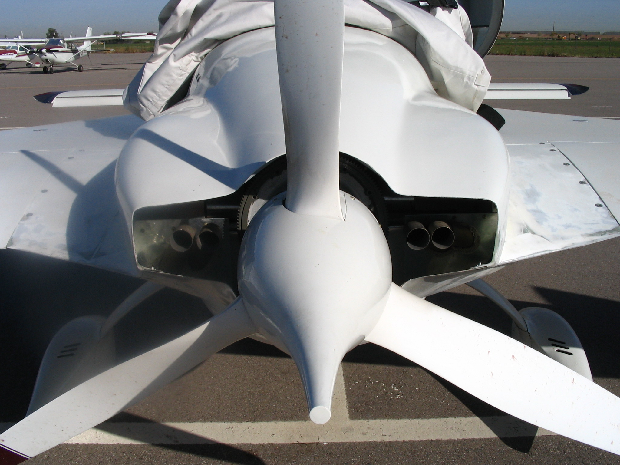
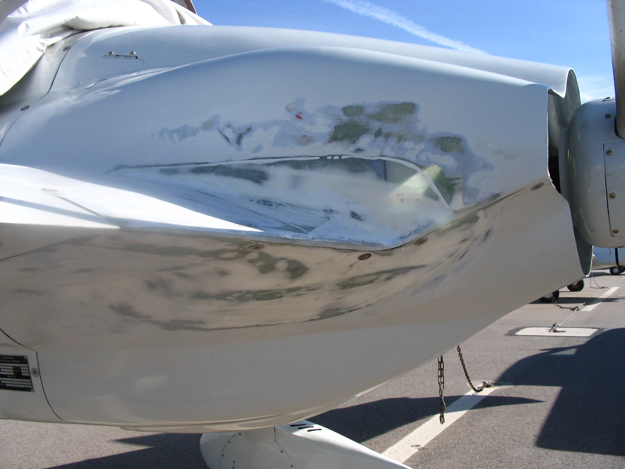
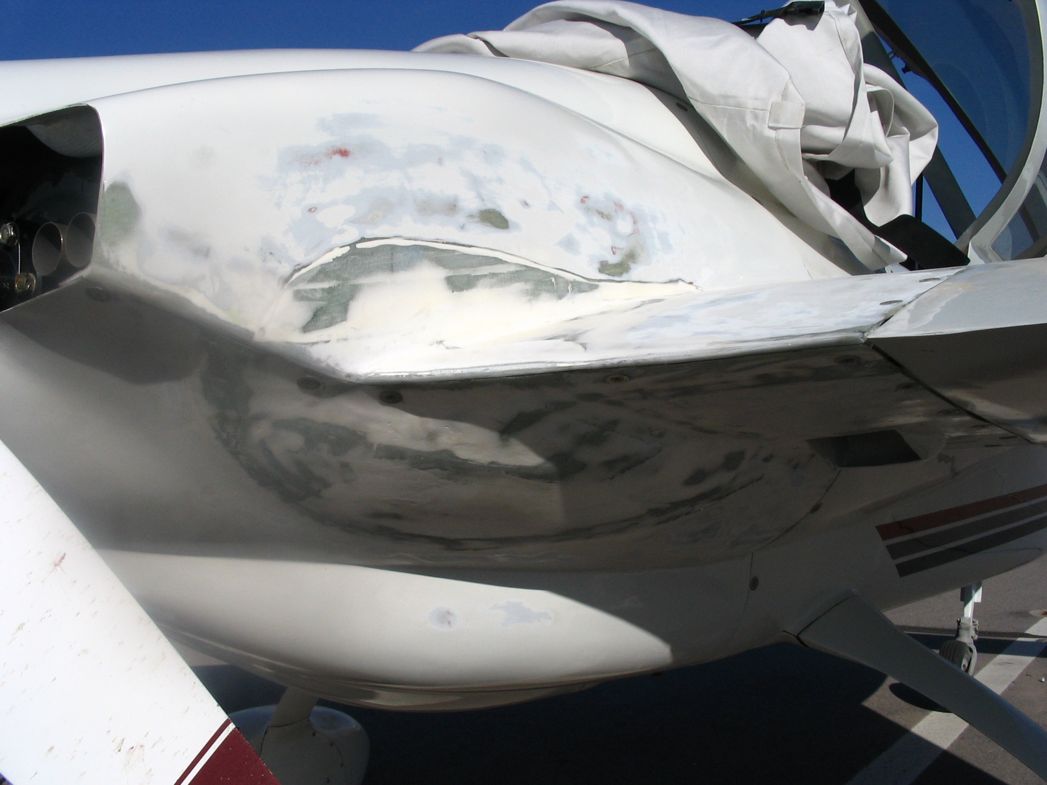
Now that the cowls were finished, I did some final trimming of the baffles and added the cowl chaffing material around the perimeter to ensure an airtight seal. Final fitting of the cowl occurred in early April of 2005 and I test flew the plane on April 11, 2005. Follow this link for info on the test flight and my unfortunate gear up landing!
After repairing the nose damage and finished painting the cowls. The end result is a cleaner looking cowl and I'm happy with it. One thing I have noticed in flying it now for 10+ hours is that the soot is more pronounced on the blade root. Not a big deal, but it should be expected as the blade is actually in the exhaust stream longer since the pipes were moved inboard. A quick wipe of the blades after a flight is generally all that's needed to get it looking clean.
Last Updated on July 12, 2008