Chapter 9
Main Landing Gear, Brakes
Main Gear Fabrication/Installation
The Main landing gear consumes most of this chapter. I was considering a retractable system, but decided to forgo that (at least for now) and stick with the plans version of the fixed gear. I purchased the wheels and brakes (Matco) and tires and tubes (Michelin) from Infinity Aerospace and the main gear legs from AeroCad. Jeff at AeroCad will build up the gear legs a few different ways; the basic gear is right out of the mold, the second way is with the gear cut and glassed with the first 4-ply UNI lay-up complete. The third is a complete gear with the tabs and everything done. I chose to go with option 2 since I still want the experience of building it.
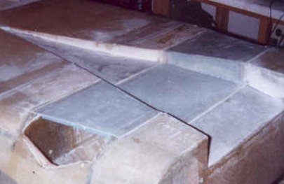
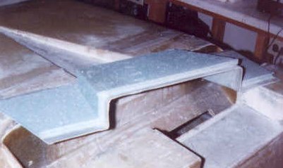
I received the gear legs from AeroCad in late spring of 1998 (along with the wing spars and cores that I purchased from them as well). Here is a picture of the gear as I received it from AeroCad.
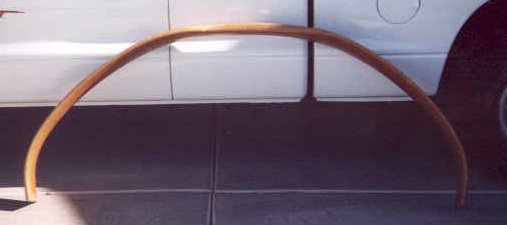
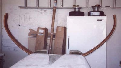
And here is the gear as it fits onto the fuselage. In this photo, the fuselage is upside down and you can see the Matco wheels and brakes and Michelin tires setting on top of the freezer in the background..
As of November of 1997 I have worked for Intel for 7 years and they have a great benefit - every 7 years you are entitled to a 8 week paid sabbatical leave! Well, this summer I took the time from July 4 through Labor Day off for my sabbatical and had a great time. We weren't home much of that time so the gear legs took longer to finish than normal. Finally though, in the first week of September, I finished the installation. Here is how it went together.
I sanded the gear and 5-minute glued some soda straws to the trailing edge to act as a conduit for the brake lines. With this in place, I layed up an aluminum tape edging on one side of the straws and made a 2 ply BID lay-up along the edging. After cure, I removed the tape and wrapped the gear with it's second 4-ply UNI lay-up, fairing in the trailing edge around the straws. Here is a photo of the gear at this stage.
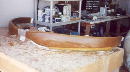
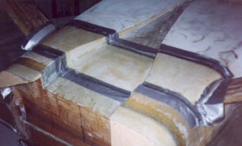
I then leveled the gear on the floor at the correct angle and built up a box on top of the gear for laying up the attach tabs. The whole thing was then lifted up onto the work bench and leveled on all sides. I taped off the box so epoxy wouldn't stick to it and layed up the scheduled plies of UNI and BID cloth for the outer tabs. You can see the lay-up in this photo as it cures with clamps in place.
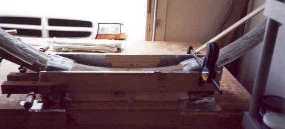
After cure, holes are drilled using a guide in each of the tabs. The tabs are rounded and sanded and the inner tabs are layed up. After this cures the tabs are once again drilled through and shaped. I then leveled the fuselage (upside down) fore and aft and side to side and set the legs into the gear well. I had already drilled matching holes in the gear bulkheads when they were built, so I took some long 1/4 inch rod and installed it through the bulkheads and tabs. With a little adjustment of one set of bulkhead holes, the gear was straight, level and at the correct angle!
I removed the gear, fabricated the aluminum MG-1's and MG-2's and installed them per plans in the bulkheads, drilling the openings out to 5/8 inch. The MKMG-4 bushings were then installed in the openings. Here's a picture showing one of the MG-2's with the bushing installed.
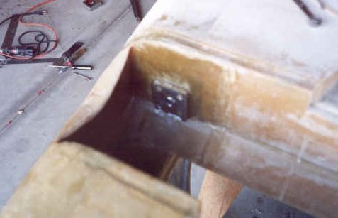
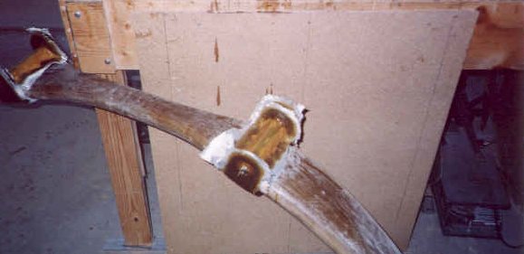
Next, I drilled out the attach tabs to 3/4 inch and installed the MKMGA tubes in the holes. I test fitted the gear back in the gear well and after insuring the gear attach bolts would slide through easily, I removed the gear and flox'd the MKMGA's in place then placed it back into the gear well for cure. After cure, the MKMGA's get a 2 ply BID wrap around a foam spacer and onto the inner gear tabs. A washer is flox'd on the outer side of the tabs and held in place with a 2 ply BID lay-up. Here is a picture of the final tab lay-ups.
Installing Axles, Wheels and Brakes
With the gear legs complete and installed in the fuselage, I re-checked the level and prepared for mounting the axles. I followed the procedure for setting the 1/4 degree wheel alignment toe-in, made a backing plate of .063 aluminum and carved away a good portion of the gear leg ends to allow access for the brake calipers. Here is a photo of the right gear leg at this stage.
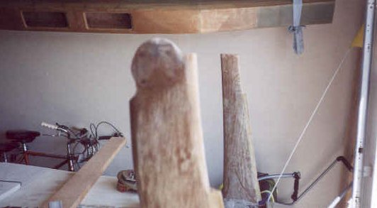
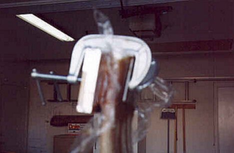
I then wrapped 3 plies of BID around the gear ends followed by a layer of flox. I attached the backing plate to the inner side of the gear leg and a flat board covered with duct tape and plastic wrap to the outer side and clamped them tight as I sighted in the toe-in using the board as a flat plate guide for my sighting tool. Satisfied that everything was correct, I cleaned up the excess flox that oozed out and let this all cure overnight. Here is a poor picture of one of the clamped legs.
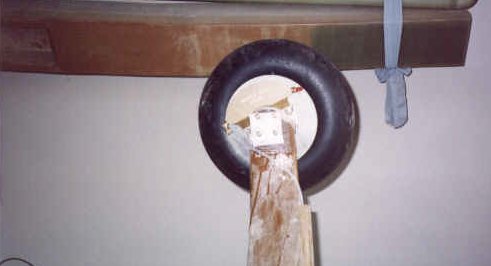
After cure and with a nice flat surface to work with, I clamped the axles to the gear legs and drilled the four mounting holes through the leg and the backing plate. I then fitted the Matco brake calipers to the gear leg and used a Dremel to grind away the gear leg ends for a good fit. I attached the axles and calipers permanently, then installed the wheels and tires to the brake disc. I ran the Nylo-flo tubing for the brake lines through the gear leg conduit and attached them to the calipers. Here is a shot of the completed installation.
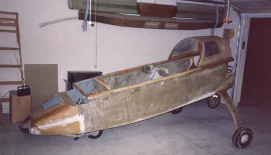
Afterward, I flipped the fuselage over with the help of my wife and set the plane on it's gear for the first time. What a sight! I then ran the brake line from the rudder pedals to the gear bulkhead along the left side of the aircraft. I'll make a bulkhead fitting for attaching the brake lines together at a later time. Here is a shot of the fuselage on it's gear in the "kneeling" position.
I decided to build the removable gear cover prior to the landing gear legs arriving from AeroCad but didn't like the way they turned out. So, I built it again. I started by laying foam into the gear opening in the bottom of the fuselage. After contouring it to the correct shape, I covered it with two layers of BID and let it cure. After trimming, I flipped it over, shaped and glassed the inside. Again, I trimmed the piece after cure and drilled about 16 holes through the cover and into the aluminum slugs imbedded in the landing gear bulkheads. These were all tapped for the screw that will eventually hold it in place. Here is the rebuilt cover glassed in place in early 1999.
Finally, the gear well is closed off by installing a lid with two access holes across the gear bulkheads on the inside of the fuselage. The lid is covered with 2 ply BID on the bottom, flox'd into position and then covered with 2 ply BID over the top and down onto the sides of the bulkheads.
Speed Brake Fabrication
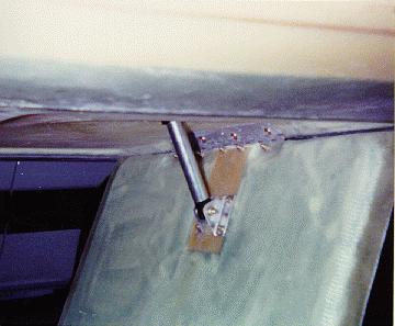
Part of this chapter deals with the speed brake fabrication. This plane is so aerodynamically clean that it is difficult to slow it down and this item is necessary to get the plane to slow down and come out of the sky at a rate of decent that doesn't require a long runway to land! I have chosen to use the electric actuated mechanism from Wayne Lanza. Before installing the mechanism, I cut loose the brake from the fuselage bottom. Remember I put it back on so that I could glass the bottom of the fuselage. I prepared the back side of the brake for the hinge and brace and rounded the corners for glassing. Here are those pictures.
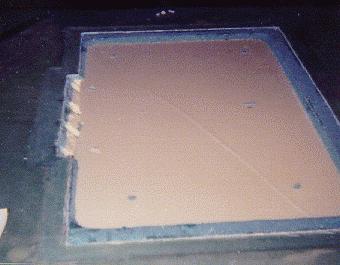
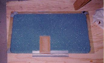
After installing them I glassed the surface and trimmed it to size. I then attached a piece of plywood to the hinge temporarily that would be flox'd into the fuselage. To prepare for this I put the brake in place and Bondo'd some boards to the brake to make sure it sat in the same spot during cure. I then routed out a place for the plywood and flox'd it in. Here are those pictures.
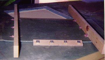
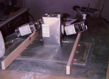
After cure I popped the brake loose and drilled and tapped the permanent holes for the bolts. I then contoured the fuselage bottom where the brake retracts, glassed it and reinstalled the brake permanently adding the actuator bracket. This is the brake prior to installing the actuator itself.
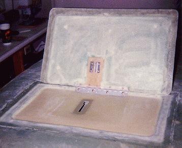
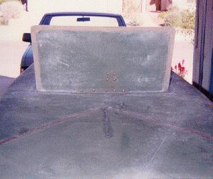
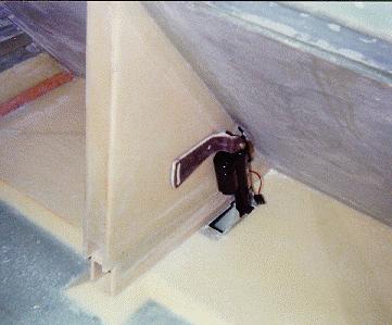
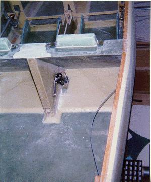
Next I turned the fuselage over and fitted the actuator. It fits alongside the seatback brace and can be adjusted as needed to make the brake open and close smoothly and fit snug. This took about an evening to accomplish. I was able to rig up the actuator to my truck's battery and made it extend and retract! It was pretty exciting! Here are a few pictures of the brake assembly.
