Chapter 16
Control System
The control system for the Mark IV is a dual control side stick configuration, similar to a fighter plane. The stick controls pitch (elevators) and roll (ailerons) and is assembled from tubing and a few universal and ball joints. The rudder controls yaw and is used in braking and is a cable actuated system. The rudders are on each winglet and are controlled independently which is different on most aircraft which have a single rudder.
The rudder cables run through a small diameter plastic tube which is routed along each side of the fuselage and extends from the firewall to the nose. The plastic tubing runs inside an electrical wiring duct which is fabricated from fiberglass by making a male plug, wrapping it in duct tape and glassing over it. Once the glass is cured the foam and tape is removed and you have a nice fiberglass channel to attach to each side of the fuselage using flox and fiberglass tape.
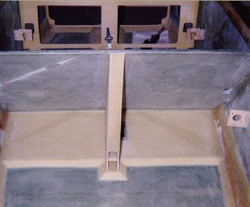
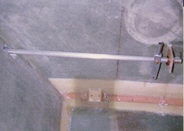
The tubing for the pitch and roll system is cut to length and small plywood blocks are cut which hold the system to the inside of the fuselage. The aileron control tubing rotates inside of these blocks which also have phenolic bushings attached to them. The tubing extends from the front seat through the seat back and then through the firewall where Oilite bearings are installed. The left and right aileron controls are then connected by a connecting rod aft of the firewall. Each wing will then have an aileron tube going to each side of the connecting rod. Here is a shot of the control system blocks attached to the side of the fuselage and a shot of the control tube and stick.


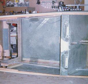
The pitch control is attached to the elevator control arm and down to the bottom of the control stick by tubing. This is a two piece linkage and can be disconnected for easy removal of the canard from the fuselage. Chapter 17 has the detail of the pitch and roll trim and includes a picture which show more detail of the control system. Here is one picture of the roll tubes as they extend through the rear of the fuselage.

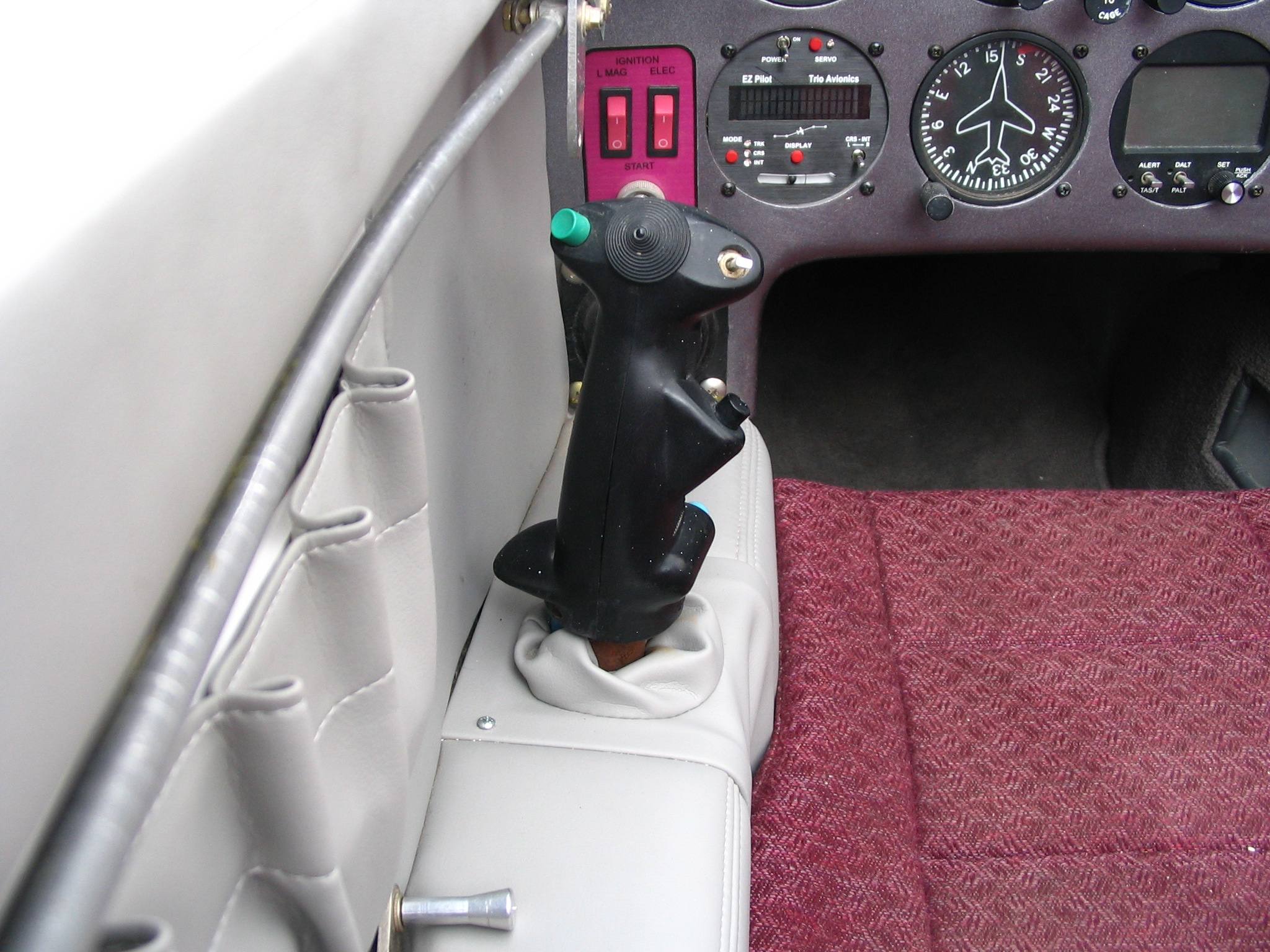
The control sticks I decided to use are made by Infinity Aerospace. These grips are scaled versions of military fighter grips and include a number of switches that can be customized for a particular plane. The diagram below shows the grip switches and what I've assigned to each switch.

-
Black 4-way hat switch - forward/backward is assigned to pitch trim, left/right is currently unassigned
-
Red trigger switch - assigned to radio push-to-talk
-
Toggle switch - assigned to electric landing brake (forward=brake up, center=off, momentary aft=brake down)
-
Black momentary pushbutton - assigned to autopilot and altitude hold servo disconnects
-
Blue momentary pushbutton - assigned to Gear/Canopy warning circuit silence
-
Green momentary pushbutton - assigned to autopilot mode switch
The co-pilots stick grip currently has only the push-to-talk switch assigned. Here are some images of the pilots side grip after the plane was completed showing the stick in full left aileron, neutral and full right aileron positions.


