Chapter 18
Canopy
After returning to the warmth of Arizona from the East coast, I cleaned out the garage and reorganized my tools and materials to get the new year (1997) off to a good start. I ordered the materials for chapter 18 and started building the turtleback form. The form is a structure which I will use to lay up the interior of the turtleback in order to get the correct size and shape. I was able to use some particle board material I had left from a previous project to build it. I am planning on modifying the canopy latch mechanism to a system used on the Glasair composite aircraft kit. It has a flush exterior door handle that pops out to unlatch and open the canopy.
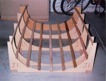
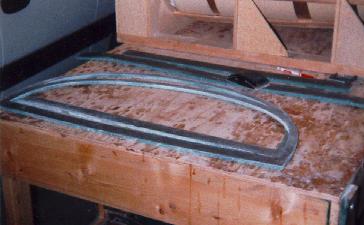
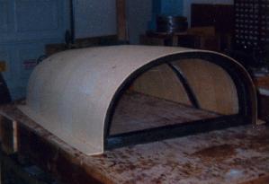
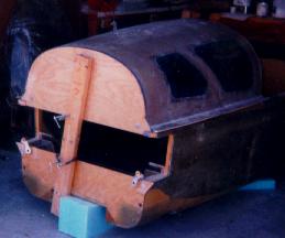
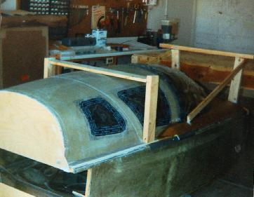
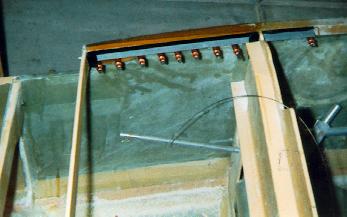
The form is built from five jigs which are bonded perpendicular to a couple of straight 2x4's. The jigs are notched to allow cross pieces of lattice to be installed, creating a "mesh". After the form was built I started to lay in pieces of 1/4 inch foam 6 inches wide starting at the front of the form. Each piece is temporarily glued in place with 5-minute epoxy and allowed to cure before the next piece is laid in. Each subsequent piece has to be sanded to make for a snug fit with the prior piece because of the contours involved. After laying in 6-7 pieces, the curvature was complete and I sanded the tops off smooth with the top of the form. I then added a 3 inch wide strip of foam along the top of the form to complete the lip. After rounding off this edge and vacuuming the foam, I taped the seams with masking tape (which does NOT want to adhere at all to the foam) so that epoxy would not run into the seams and make drips on the outside. Here are a couple of pictures of the form and the process of laying in the foam.
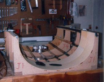
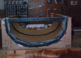
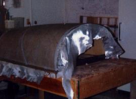
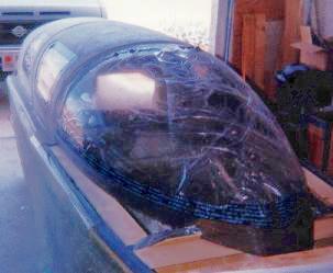
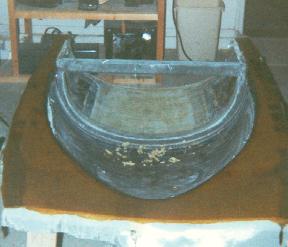
The next step was to mark two straight lines from opposing corners on the foam. This acts as a straight edge to align the fiberglass. Then I coated the foam with micro and laid up the fiberglass. This was a two ply lay-up with UNI. The fibers from the first ply were crossed by the second ply. At the appropriate time, I knife trimmed the edges and allowed the lay-up to fully cure. Here is the foam after glassing. The peel ply at the front is for attachment of the TB1 bulkhead later.
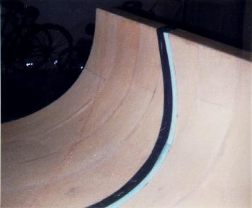
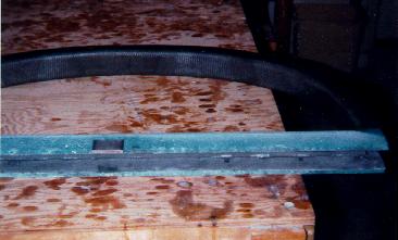
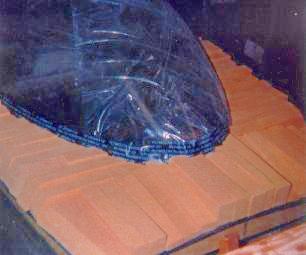
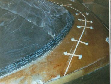
I then drew a diagonally swept-back line for where the turtleback would eventually be cut to allow the forward portion to swing open and allow for passengers to enter and exit. I placed a board across the form and clamped it in place. I then took one of the interior pieces of one of the jigs and laid it at the correct angle over the board extending down into the form. This gave me a flat reference plane for sketching the line. I took a felt pen and ran it along this plane marking the line on the inside of the form. I then drilled 1/16" holes along the line spaced approximately one inch apart to act as reference points on the outside of the turtleback. I then put duct tape along this line extending forward of it to act as a release agent for a drip rail. The rail is made of 3/8" foam cut to the appropriate shape glued to the inside of the turtleback and overlapping the cut line. This is partially covered with duct tape and then glassed over with BID and allowed to cure. The tape will allow the foam to be removed later leaving just the fiberglass drip rail. Here is the drip rail prior to glassing.
After some consultation with fellow builders, I decided to modify the TB1 bulkhead which supports the front of the turtleback. The plans call for a bulkhead that, in my opinion, hinders the rear seat passenger's view forward. I modified it by taking the bulk of the center of the bulkhead away leaving just the outer 1 inch along the curved portion and a 2 in edge along the bottom. I made two of these and mated them together to get the contours to be perfectly matched. I then glassed the facing sides of each with 2 plies of BID and an additional 1 ply of UNI along the bottom. I also made two 2-1/4 in wide strips of 3/8 in thick foam, one approximately 32 inches long and the other approximately 49 inches long. I glassed them on one side with 2 plies of BID and allowed everything to cure. I then stood the bulkheads up with the glassed sides facing each other and flox'd the 32" long strip (glass side down) to the inner bottom edges to form a C channel 2-1/4 inches wide. I then flox'd the 49 inch piece against the curved inner edges to complete the C channel all around the bulkhead. I clamped everything together and let it cure. Here are photo's of this sequence.
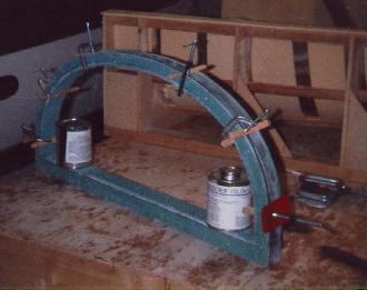
Next I flox'd in a piece of 1/4 inch thick aluminum 2x1-1/4 inches centered 18-1/4 inches from the right side of the rear facing bulkhead piece by removing the foam at that location and flush with the bottom of the bulkhead. This will eventually be drilled and tapped for a ball lug for a gas compression spring used to hold the canopy open when entering and exiting the cockpit. I then rounded all the inner edges of the C channel and glassed with 3 plies of BID all over with one additional ply of UNI running along the bottom flat edge. I also reinforced the area over the aluminum insert with 2 plies of BID. At this point I had a solid C channel bulkhead that I flox'd into the turtleback form with the front side 2-1/2 inches from the front of the turtleback. I then completed the bulkhead installation by taping all around the edges on both sides with 2 plies of BID. This is the bulkhead with the aluminum insert showing prior to glassing that section and then the completed bulkhead after glassing in the turtleback form.
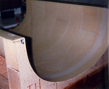
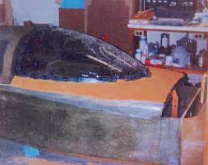
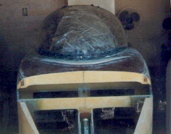
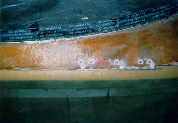
I then trimmed all the edges of the turtleback and removed it from the form after cutting the foam loose where I had tacked it down with 5-minute epoxy. I layed it on my table and secured it so that I could prepare the outside for glassing. The foam was sanded to get rid of bumps and joggles and a depression was sanded across the cut line, at the front edge where the canopy will later attach and at the aft end where the cowling lip is located. I then sketched a cut line using the holes I previously drilled as reference so I could see where to cut after glassing. After filling any irregularities with micro, I glassed 2 plies of UNI (same as on inside surface) over the outer surface, trimmed the edges and allowed it to cure. Here is the turtleback prior to shaping as well as a picture of it being glassed.
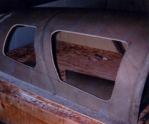
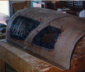
My canopy and windows arrived just in time from Foxlite (Airplane Plastics) to prepare for installation. It was really cool to put the turtleback and canopy on the fuselage during a test fit! It's actually looking like an airplane! The side windows are drape molded to the shape of the turtleback by Foxlite. I marked both sides of the fuselage where the windows would go per the plans, then took my hand held jig saw and cut out the openings to within 1/8 inch of the final size. I then took my grinding wheel and a straight edge to get the opening to the final size. After cutting all four openings, I removed one inch of fiberglass and foam from the inside surface of the turtleback at the largest opening of the window and also routed out about 3/4 inch of foam from the perimeter of the openings. This allowed the window to be slid into the opening I just created. I test fitted all the windows, then taped off each window to protect the surfaces. I then mixed up some flox, placed it in the grooves and around the perimeter of the windows and slid them back in place. I secured them while they cured with cleco's. After the flox cured, I sanded the areas around the inside of the windows, replaced the 1 inch of fiberglass at the area it was removed from and glassed 1 ply of BID over it. Here are some more pictures.
With the windows in place, I then flox'd my upper firewall to the fuselage. The plans would have you install the main spar prior to this step, but I am going to do it without the spar so that I can continue to work on the fuselage. I will begin the wings after the fuselage is completed. Anyway, the upper firewall is flox'd into position and held vertical to the lower firewall by a couple of straight boards clamped or Bondo'd in place. I chose to clamp mine. The only area of flox is where the firewall meets the longerons, so there is not a lot of area to bond to. I let the firewall cure for a couple of days and then test fitted the turtleback to the fuselage.
I shimmed the turtleback 1/16" (stir sticks work great for this) above the longerons and made sure everything was straight and level. I trimmed the aft edge of the turtleback so that there was a tight fit between it and the firewall. I mixed up a large batch of flox and proceeded to spread it on the longerons from the future cut line to the firewall. I also removed some foam at the aft end of the turtleback, filled it with flox and then mated the turtleback to the fuselage. I cleaned up the excess flox that oozed out and also filled in areas that were "lean". I then concentrated my effort on the firewall interface. I had to drill a few alignment holes near the edges that penetrated the turtleback foam. I placed 2" finish nails in the holes to ensure that the turtleback conformed to the firewall shape without bowing outward. I had to do this mostly on the lower edges of the turtleback and as I worked myself upward to the top of the firewall, the turtleback fit nicely without any help. I made a nice round of flox at the joint and allowed this to cure for about 6 hours. The flox was pretty stiff by then and I could pull the nails out. I then let everything cure for 2 days. Afterward I cut and sanded the turtleback flange from the firewall to the future cut line so that it matched to shape of the fuselage sides, filled the gaps with flox and glassed two ply's of BID over this joint. I also glassed over the joint at the firewall and turtleback after sanding everything nice and smooth. I will return at a later time to glass the joint from the inside as well. Here is the firewall and turtleback flox'd in place.
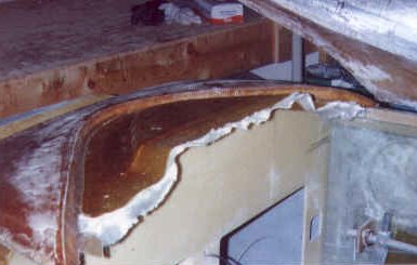
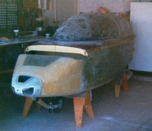
I got my canopy out and test fitted it to the turtleback. I increased the height of the turtleback by an inch when I built it and so the canopy doesn't need any trimming at the shoulder support area. I still had to trim it where it fits over the instrument panel by nearly two inches. I used a grinding wheel in my Dremel to slowly grind away that area of the canopy. When everything fit nicely and the contour was correct per the canopy template, I marked a tape line around the lower edge of the canopy using templates as called for in the plans. I then connected the line with thick rubber tape making sure everything looked nice and smooth. I also applied tape near the aft end of the canopy where it mates to the turtleback. The canopy was then sanded with 220 grit inside and out at this end to prepare it for bonding. Next I used duct tape to mask off some areas along the fuselage longerons, instrument panel and across F-28. I then Bondo'd some flat 4" wide boards along the fuselage insides from the shoulder support to the instrument panel even with the taped longerons and also cross ways aft of F-28 and forward of the instrument panel. This will be for supporting foam in a later step. I checked the fit of the canopy one more time and then flox'd it in place on the turtleback. Wow! It's actually looking like something other than a boat! See for yourself.
After the flox cured, I sanded the rough spots and laid up a layer of UNI along the lower edge of the canopy, butting the selvage against the tape for a smooth line and extending the glass onto the fuselage 2 inches. I then laid up 3 layers of BID across the aft end of the canopy onto the fuselage. This was peel ply'd and allowed to cure.
The canopy fairing into the fuselage body is made by stacking blocks of foam all around the perimeter of the canopy and then sanding them to contour. I started on one side of the fuselage stacking these blocks next to each other and continued around the front and back along the other side. This process is actually quite time consuming since it involves fitting 2 inch wide blocks up against the curvature of the canopy and slowly sanding then to get a nice snug fit. Each block is different, so you just have to go slow and steady. Once I got the foam blocks set in, I removed them all and laid up a sheet of wax paper where the blocks would sit on the fuselage and boards. I then micro'd the blocks together as I reinstalled them in their locations. After all that cured, I started to sand the blocks to contour using the checking templates. After I was satisfied with the result, I dug a small groove along the top between the foam and canopy. This groove will become a flox corner later. I then glassed the foam with one ply of BID with the edge going down into the groove. I then filled the groove with flox and followed that with a second ply BID. This ply was taken over the flox up to the edge of the canopy. I followed that layer with two plies of UNI. This took longer than I anticipated, but since this is an area that people will have a tendency to see up close, I took my time and tried to remain patient. The next morning I knife trimmed the lay-up along the edges. Here are a couple of pictures of the foam blocks fitted in place and after rough shaping.
This lay-up was allowed to cure for two days after which I cut through the cut line on the turtleback to separate the front and rear halves. I tried to carefully cut it without cutting the drip rail, but in a couple of places I went through it too! No problem - it gets two more layers of BID anyway to seal off the cut. I also popped loose the rest of the canopy where it was sticking due to drips and after I was sure it was free I began to build a frame around the canopy to aid in working on the inside. The frame is just a few 2X4's Bondo'd on to act as legs. They are cross braced as necessary. I then lifted the canopy off the fuselage and turned it on its "legs" onto my work table.
The interior of the canopy gets a few coats of Spraylat to protect the Plexiglas. I started to contour the foam on the inside and prepared areas to lay in flox/BID hard points for canopy latch hardware and hinge attachment. I also ground down the canopy to final contour. After getting the foam correct, I installed the hardpoints and let them cure. Then I laid up the interior glass lay-up which is identical to the external lay-up - 2 BID & 2 UNI.
After trim and cure I prepared the fuselage so that I can remove the front portion of the canopy piece for aid in getting to the instruments. This involves adding some spruce and hinges between F-28 and the instrument panel. I then fitted the canopy back on the fuselage, squared it up and made four locating pin holes on each corner. I then flox'd the hinges to the canopy and let it cure. Next I cut through the front of the canopy top, opened the cut up to 1/8 inch and temporarily "stuck" it all back together as one piece with Bondo. I then took the canopy back to my work table and finished the removable cover details, installed a drip rail, finished off foam edges and bolted the hinges to the canopy frame. I trimmed the drip rail and added the details necessary to attach the removable cover.
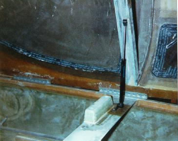
After what seemed like an eternal hiatus from the project so that I could add a room to my house to make room for the next little DeFord due in December, I added the gas compression spring and hardware to the turtleback bulkhead. It works as designed and is completely hidden when the canopy is closed.
I also added two air scoops to each side of the fuselage for cabin ventilation. The scoops route to small "eyeball" vents in the instrument panel. Next I fabricated an instrument panel cover by forming some foam and laying on a couple of layers of glass. After removing the foam form and trimming, I added a couple of clips with rivets. This is a removable cover that allows access to the rear of the panel without removing the nose top.
Updated 5/27/2005: Details of the removable instrument panel cover:
Some folks on one of the canard forums asked me to show some details of the instrument cover and how it is attached. Below are some pictures of the cover I took after the plane was completed. Normally this cover is attached by screws to the F28 bulkhead but they cannot be accessed unless the canard is removed! So much for a "removable" cover - so I made a modification to make it removable without taking off the canard. The first picture shows the canard cover in place on the fuselage.
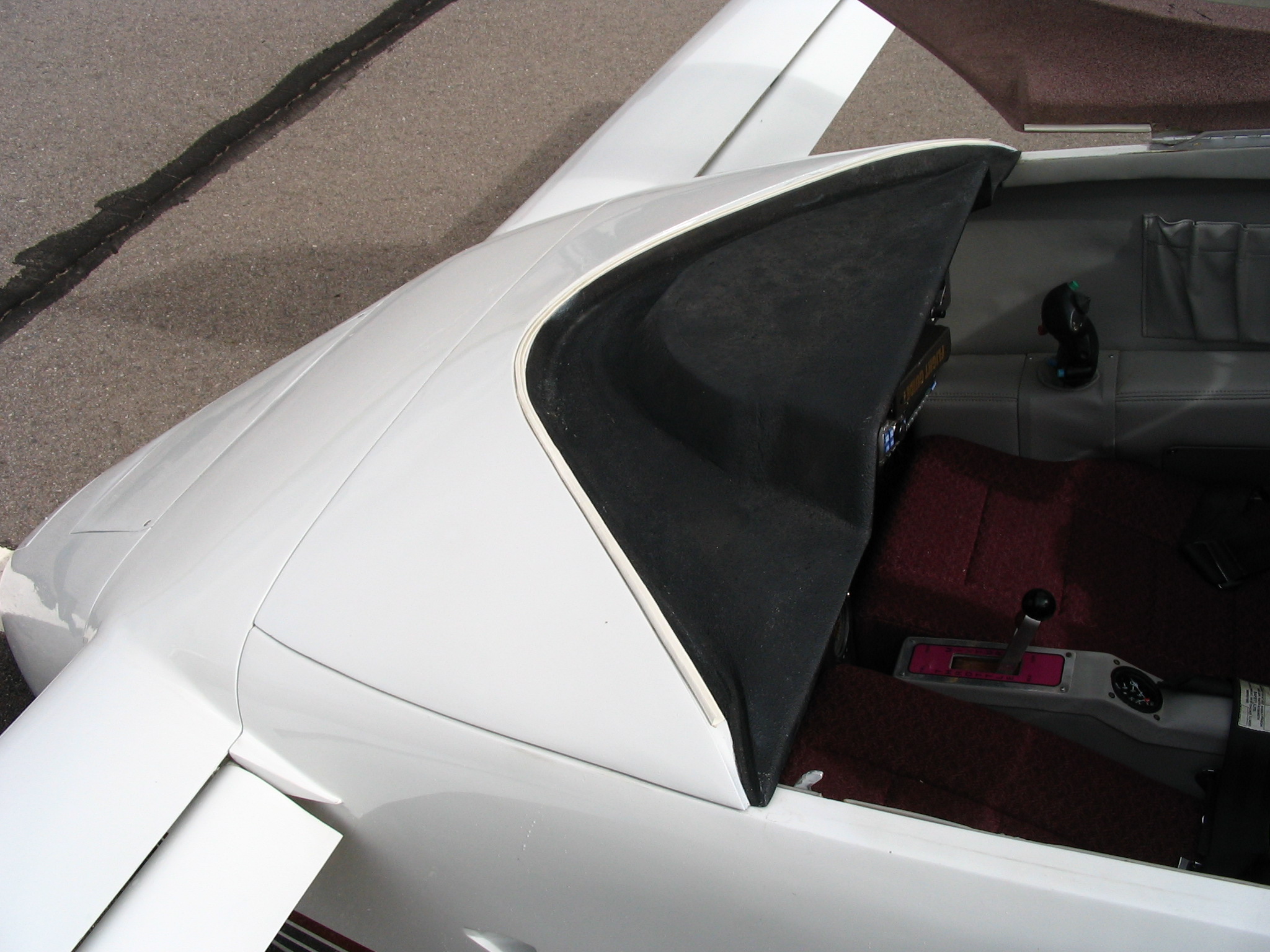
The next photo shows the front lip of the cover - about 1/4 - 3/8" wide, it overlaps the canard which also has a small lip which overlaps F28. The final joint is aligned with the aft edge of the canard.

This photo show the cover removed. You can see the side hinges along the upper longerons. Two hinge pins are pulled from inside the cabin to release the sides of the canopy. You can also barely make out the small lip of the canard covering F28. The instruments looked crowded, don't they?

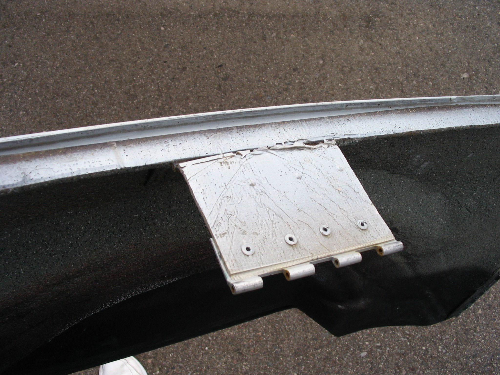
The next two photos show the front tab and hinge. A small, ~6 inch wide tab is glassed onto the bottom front edge of the cover and lays flat against the aft side of F28. The other half of the hinge is attached to the bottom edge of F28. The hinge pin is pulled (the hardest part) from either inside the cabin by reaching up under the panel or from inside the nose cover and reaching up under the canard to pull it out. Once all three hinges have been removed, the panel cover comes right off.

These next photos show the general area where the other half of the hinge is buries. It isn't easy to see in the first two pictures because it is at the bottom edge of F28 and behind the UPSAT CNX80 (now Garmin GNS480).
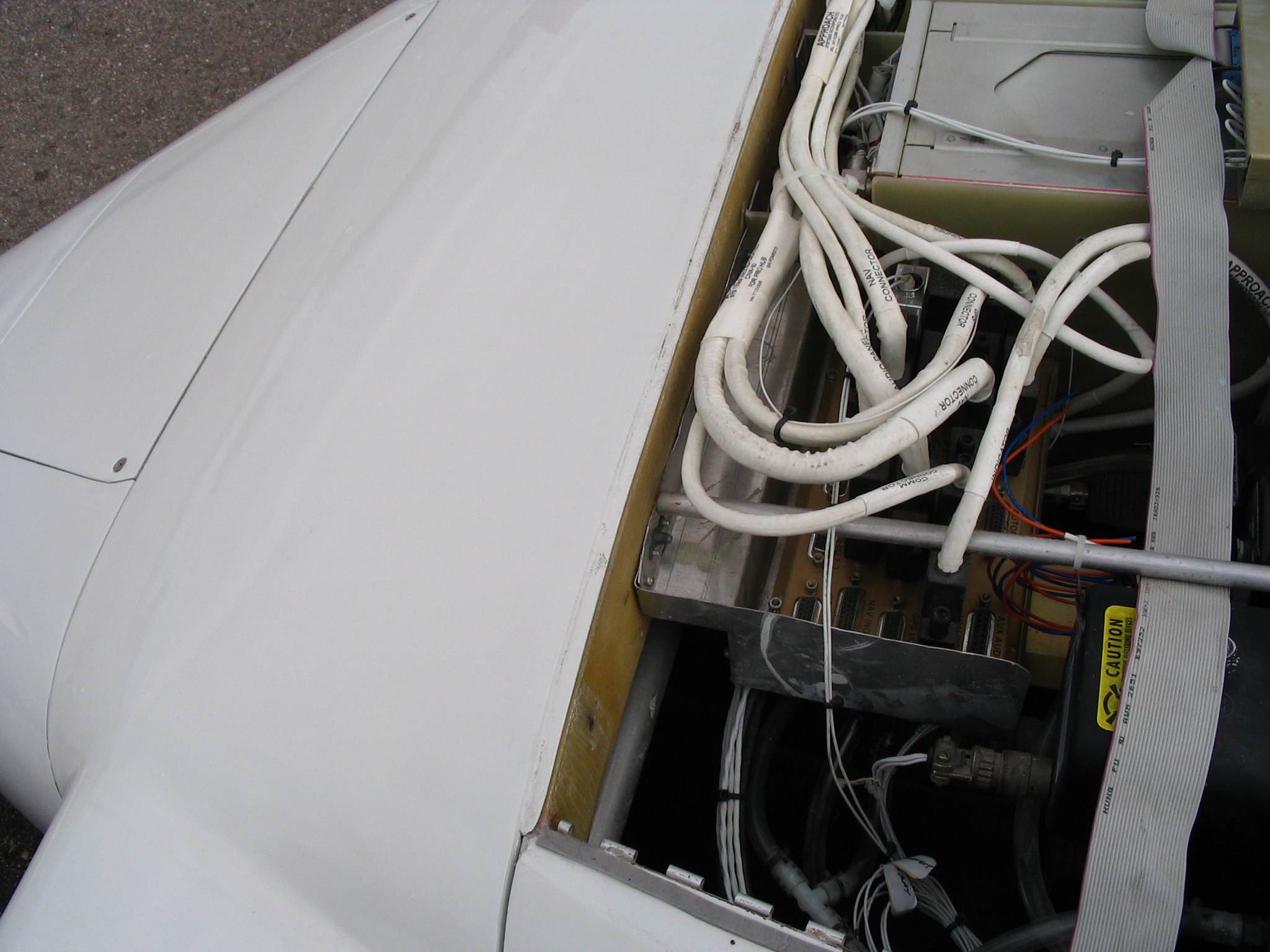

This last photo is an attempt to show the hinge down behind the radio. You can also see the canard lip overlapping F28 in this photo.

Canopy Latches (May, 2001):
The stock canopy latch system is comprised of three hook shaped aluminum latches attached to the pilot side longeron and tied together with metal tubing so that they all work in unison. The foremost latch is just forward of the stick grip fuselage wall depression. It has a longer length and is used as the handle to actuate the system. The canopy has attached to it a corresponding bolt that the latches pull down and engage when the canopy is closed and the handle pushed forward. To lock the canopy from opening in flight, the handle is pressed into a metal tab attached to the instrument panel that effectively prevents it from being pulled back inadvertently. To open the canopy, the tab is pushed away and the handle pulled back. A small door is built into the side of the fuselage to allow one to access the mechanism from outside. Open the door, reach into the aircraft and actuate the handle.
Ok, this system works perfectly fine and is simple. No reason to monkey with it, right? Well, I never liked the small door in the side of the fuselage. If you ever watch someone open the canopy by putting their hand through this little door and messing with the handle, it isn't the most elegant sight. Besides, I'd heard the air coming in around the door gaps was cold and blows right on your hand on the stick unless it is perfectly sealed. I always liked the looks of the Glasair door handle - it is a flush mounted handle, easily operated from the outside by pulling up or down to lock or unlock. The inside mechanism is a corresponding handle that is spring loaded in both the open and closed positions. I ordered the door mechanism through a local Glasair builder assistance center and then tried to figure out how to make it work in the Cozy!
The Glasair handle is intended to be a part of the door and the locking mechanism pushes pins outward from the sides of the door into bushings mounted in the fuselage sides to lock the door. The Cozy has a clam shell canopy, so the pin mechanism didn't appear to be the best approach and the latches made for the Cozy are actually very simple and lightweight. The trick was to get the Glasair handle mounted in the fuselage wall and actuate the Cozy latches. The answer finally came to me after about two years of pondering about it off and on. After installing the push-pull throttle and mixture cables to the engine, I realized I could take a similar cable and attach it to the handle mechanism. The cable could then be routed to the canopy latches to actuate them. I only needed about three feet of cable, so I purchased an aftermarket clutch cable from a performance automotive store.
The flush handle was the most difficult part to assemble because I need to make a fiberglass pocket for it. I studied the Glasair instruction sheet to see how it was all laid out in their doors and fabricated an assembly about 4 inches by 8 inches in size. The moment I dreaded most was making the decision to cut away the side of the fuselage to mount this assembly! I cut away the outer skin in the 4x8 area I wanted the handle. Then I selectively removed foam from the wall of the fuselage to allow the assembly to fit in. After getting the right fit, I flox'd the assembly to the fuselage and clamped it in place. After it cured I glassed two layers of UNI glass over the assembly and fuselage side to reinforce it. Attaching the cable was straightforward. I looped it through the wire bundle hole in the bottom of the instrument panel, up and back around through the top corner of the panel under the longeron. I mounted a cable clamp under the longeron just forward of the instrument panel to secure it. The cable then was bolted to the forward latch in a hole that was already present.
Well, the handle works perfectly! I couldn't be more pleased. Here are a couple of pictures to help visualize the above ramblings...
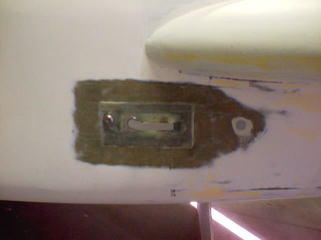
Flush mounted door handle prior to filling and priming it to blend with the rest of the fuselage side. Pulling handle down 90 degrees will unlatch the door. Pulling handle up 90 degrees latches it. A simple key lock is installed forward of the handle.
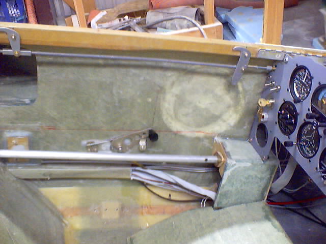
Interior view of handle mechanism. The red cable on the lower right of this picture is the push-pull cable that ties the handle to the latches. The forward latch has been modified to make it smaller since it is not longer needed as a handle. I may eventually replace it with a latch of the same style as the one seen just above the strake cutout. The interior handle will be hidden under the pilots arm rest. The black handle knob is always visible and accessible above the armrest. Notice that their is no access door needed to use this system!