Chapter 21
Fuel and Baggage Strake
After mounting the center section spar in the fuselage, I started fabricating the ribs for the strakes. The strakes act as the fuel tanks, holding 30 gallons each. The ribs act as stiffeners and also baffles so that the fuel doesn't shift suddenly to one side in a turn.
The ribs are 3/8 inch H45 foam covered on each side with one ply of BID. After cure, I sanded the rib edges to get them to their final shape. I then cut the foam for the tops and bottoms of the stakes from the same type of foam.
At this point I took my work table and butted it up against the left side of the fuselage underneath the future location of the strake. I leveled the fuselage fore and aft and side to side and then leveled the table against it. The table will act as a jig so it is important to get it leveled accurately. When everything was just right, I bondo'd the table to the fuselage so it wouldn't move. I also attached a wood board along where the leading edge of the strake would lay to act as a support when everything was being floxed together.
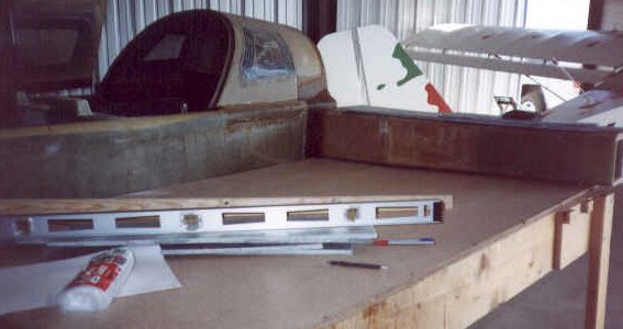
I test fitted the bottom strake foam against the fuselage and spar and beveled the aft edge so it would fit up under the spar. I then marked the spar with some butt line measurements to act as guides and test fitted all the ribs to make sure everything was good. No problems! I then marked the fuel sump area on the foam and cut a 1-1/4 inch diameter hole, beveling the edge of the hole outward approximately 1-1/2 inches. I then removed the bottom foam and glassed the top surface with 1 ply of BID.
After cure and trimming, I scored the leading edge back about 6 inches so that it would bend to the correct shape around the ribs. This was done by cutting the foam down to the glass (but not through the glass) in straight lines parallel to the leading edge and spaced about an inch apart. I mixed up a generous amount of flox and coated the aft edge of the bottom foam. I then re-assembled the bottom foam under the spar and made a flox corner. Next I floxed into position the airfoil shaped ribs and made sure the bottom foam curved up against the ribs by placing a few shims under the foam. I weighted the ribs down using a heavy plywood board laid across the top and allowed this to cure. I also floxed the edge of the foam against the side of the fuselage. The next day I floxed into position the remainder of the baffles and ribs and allowed this to cure. I decided that this was a good place to move over to the right side of the fuselage and repeat the steps for the right strake. I then sanded everything good and vacuumed up the debris. I coated all inner surfaces with a layer of epoxy, using a squeegee to fill any pinholes that may be present. I then added a 2 inch wide BID tape joint at each intersection of the bottom, ribs, baffles and spar. After this became tacky, I applied another coat of epoxy. Just to be safe - I did a third coat after the second coat was tacky. I now have both strake bottoms attached and all ribs and baffles installed.
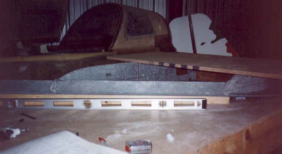
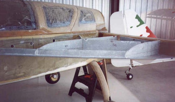
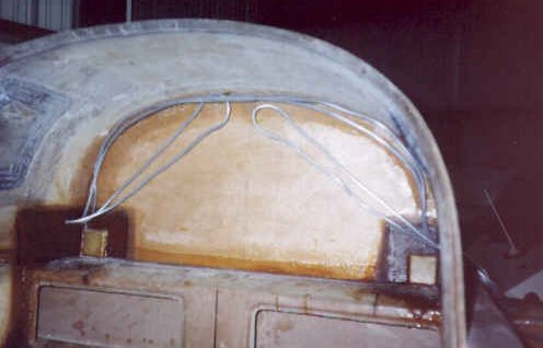
Prior to attaching the top strake skin, mixed up some pour foam and poured it into the area at the aft outboard end of the strake as called for in the plans. This is done for CG purposes. I let it get hard then sanded it down level with the baffles. I then routed the fuel vent lines for each tank. I ran two lines per tank as suggested in the Cozy mail list archives (so fuel doesn't leak out in the parked position) and routed them up into the fuselage along the forward side of the firewall to the highest point on the firewall and then back down - one to the same side as it came from and the other to the opposite side. Both vent line on each side exit the fuselage next to where they entered, run along the aft side of the spar and exit below the outer wing attach mount locations. I also floxed in place a metal strainer over the fuel sump depression on each tank to catch any big chunks of gunk that may get into the tank. I then marked where the top strake foam/skin would come in contact with the fuselage and temporarily glued some foam to the fuselage to act as a support for the skin while it was curing in place. I also marked and cut away some of the areas on the fuselage side that allow access into the strake for small carry-on luggage (OK- maybe a light jacket and a book or two). I was now ready for the strake tops!
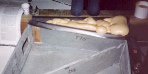
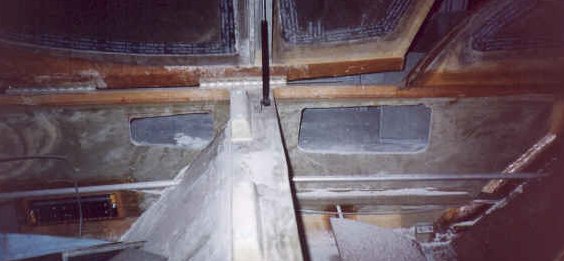
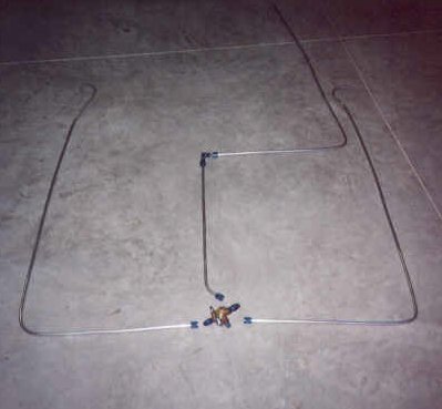
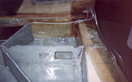
I fitted the foam to the left strake to make sure I had a good fit and that the ribs and baffles all made good contact. I then glassed the bottom side of the foam with 1 ply of BID and let it cure. I then cut the fuel cap filler holes and also fabricated a cone shaped fuel level sender mount. This was attached to the inside of the tank and will keep the fuel level sender below the level of the skin surface. I scored the leading edge (back about 11 inches this time) using the same technique as before. I then fitted the foam in place and clamped it down using a variety of weighty devices and built up a wooden frame to help hold the curved shape. This was held together with bondo. After the bondo cured I lifted the whole assembly off and turned in inside up so I could paint the entire surface with a wet coat of epoxy. While that was getting tacky I mixed up some wet flox and stacked it 1/2" high or so along all the baffle top edges, spar contact area and the pour foam surface. Then I took the top skin and laid it back onto the baffles, pushed it down good and firm and weighted it securely in place. I had quite a bit of flox ooze out at all the edges, so I am confident of a good joint. I also tried something not in the plans - I held down some of the curved parts that wanted to bulge with drywall screws. I figured it wouldn't cause a leak if the area between the joint had plenty of flox. We'll see! I taped each exposed joint with BID tape and let it all cure for a couple of days. I then repeated the whole process on the right strake.
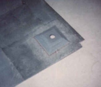
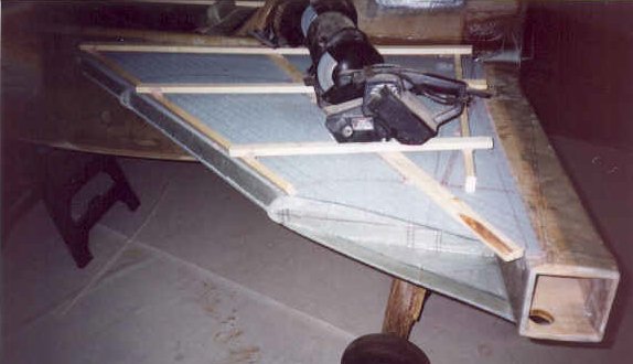
I finished cutting the access holes to their final shape in the fuselage, taped the edges and filled a few lingering gaps with flox. I removed the drywall screws helping to hold the skin in place and filled the holes with micro. I also built the OD baffles and installed them with flox at the ends of each strake. I then had a couple of friends help me turn the fuselage over so I could glass the belly side of the strakes. This layup consists of 3 plies of UNI per side lapping onto the leading edge baffles, fuselage side and spar. I fabricated fuel sumps under each drain hole and later foxed and taped them in place permanently. I also added a fairing to blend this sump into the airframe.
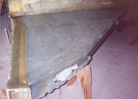
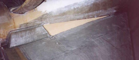
At this point the plans would have you turn the fuselage back over and glass the top of the strake, but I had some detail work to finish on the belly of the fuselage. I got my first flight in a Cozy MK-IV at this point in the project! Nat Puffer, the designer of the Cozy, lives just a few miles away in Mesa, Arizona and has been kind enough to act as my EAA technical advisor. I met Nat at his hangar at Falcon Field Airport and we flew his plane to my hangar in Chandler. It was about a 10 minute flight but what a thrill! Nat allowed me to fly immediately after takeoff and took over again when it was time to land. I'll have to say the ride gave me a big boost and I've been itching to get to the hangar every day since then. In fact, I purchased the engine the next week day, picked up my cowling from the shipper the following day and can't wait for it all to be installed.
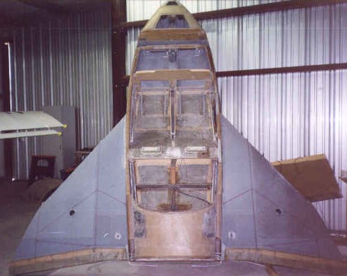
After completing the details on the belly of the fuselage, I turned the fuselage back over and glassed the tops of the strakes as called out in the plans. There is one extra ply of glass on the top of the strake to help strengthen it when walking on the strake. Other than that it is identical to the bottom glass lay-ups. The areas where the fuel sensor probes were installed were modified so that I had a channel to plumb the wires from the sensor through to the firewall. I also created a slight depression in the fuel filler cap area so that the cap ring would sit flush with the surface. I wrapped the cap ring in plastic wrap and weighted it in place while the glass cured. Now it is time for the infamous pressure check!
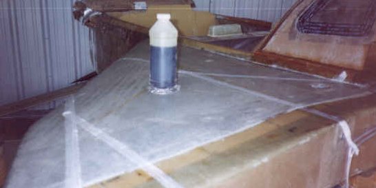
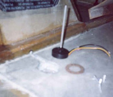
The pressure check is done to make sure no leaks exist for fuel to flow out of. What a pain that would be! I connected the fuel lines coming into the fuselage to the valve and turned the valve to the "both off" position. I then used hose clamps to attach 6 foot long pieces of 3/8" ID clear vinyl tubing to each fuel return line I installed to accommodate the fuel injection. The tubes dropped down about a foot and then straight back up and were held in place with a board and clamps. I took 1/4" ID clear vinyl tubing and clamped both of the tank vents from each tank together (remember I had two vents per tank). I installed a "T" fitting in each line and connected another piece of tubing to this joint. I used that tube to blow air into the tank.
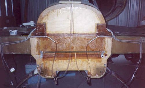
The process went like this: I would pour colored water into the 3/8" ID tube so that about 25 inches of the tube had water in it. I marked where the water line was with no pressure, then measured up 18 inches. I then blew air into the 1/4" ID tube until the column of water rose to the 18 inch mark. This was equal to 18" of water pressure. I then watched the column to see if it fell. Over the course of a day the level should rise or fall due to temperature and outside air pressure changes, but should not continually drop.
Both tanks were tested at the same time. The first test revealed that both gas caps leaked, so I greased them both with lithium grease and re-installed them. On the second test, both fuel drain valves were leaking at the joint. I let all the pressure off the tanks and sucked a vacuum on each one. While the tank had vacuum, I brushed epoxy on the valve joints and let the epoxy draw into the leak. I then let off the vacuum and allowed the epoxy to cure. On the third test, both joints were fixed, but I still had a relatively large leak in the left tank. I found this with relative ease - it was at the junction of the tank to fuselage baggage cutout. I had forgotten to tape this joint with epoxy! SO - I let off the pressure, taped the joints and allowed it to cure. On the fourth test the left tank was perfectly sealed - No Leaks! The right tank had a very small leak (on the order of losing 1/2" an hour). I couldn't trace it using soapy water or by ear, so I decided to take a break and work on something else for a while. Lo and behold, after coming back a couple of days later, the tank no longer leaked! Now that is strange. I pressurized the tank and could not get the tank to leak, so I shook the airplane to see if there was something loose or not quite sealed all the time. That caused the tank to lose a couple of inches over the course of a day. Finally I was able to detect a small leak at the drain valve again. I sealed it and pressure checked the tank. After two days there was no leak even after shaking the plane.
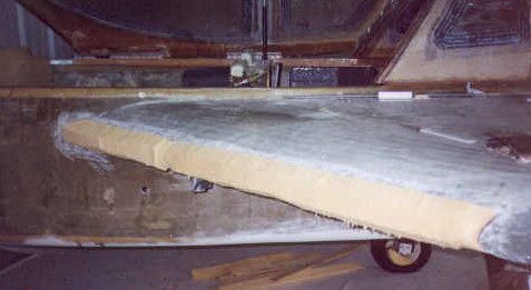
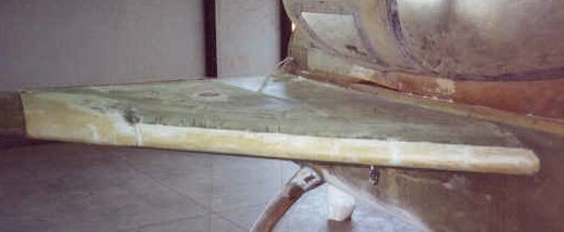
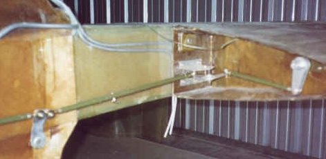
I'm confident the tanks are good and sealed and so I am off to the next step - building the leading edge of the strakes. This is done by bonding foam to the leading edge of the strake and contouring it to the correct airfoil shape dictated by the strake bulkheads. I built a long sanding spline for this operation. After contouring the foam, I glassed each leading edge with two plies of UNI at 45 degree angles, using peal ply to transition the edges. The last step in this chapter involves building a filler block to transition the strake into the wing at the leading edge. I attached the wings to the fuselage and built up the area with foam, then applied 2 layers of glass over the foam. After trimming, the wing to strake transition is complete. I then built and installed the final aileron control tubes and rudder control connections with the wings attached.
