Chapter 23
Engine and Propeller Installation
After what has seemed like an eternity, I finally settled on an engine choice for the airplane and ordered it. The engine will start as a Lycoming straight angle valve O-360 A4G (solid crank) remanufactured by Aero Sport Power of Kamloops, BC. Many other folks have had good comments about them and I have to agree. This engine will come equipped with overhauled cylinders, 1 Slick magneto, harness, Light Speed Engineering Electronic ignition (replacing the other magneto), new plugs, fuel pump, Airflow Performance fuel injection, light weight starter, inter-cylinder baffles, ring gear, vacuum pump adapter, oil filter screen and new crankshaft. Due to the changes to the engine, it is now technically a Lycoming IO-360-B4A. I will also be using spark plug adapters to convert from aircraft size plugs to automotive size plugs. These changes added a few $$ to the price of the engine, but it is everything I want. For those who just have to know - this setup cost me $18,000 (ouch!) in May of 1999.
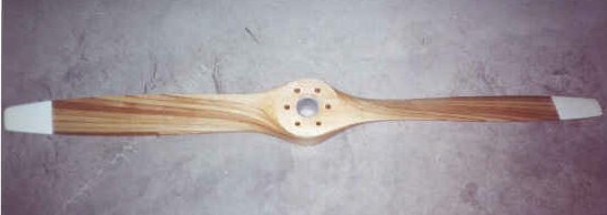
Of course there is more than an engine that makes up this chapter, so I ordered the cowlings as well as a propeller. Here's a picture of the original two bladed Sensenich prop.
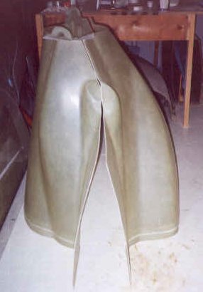
As well as the stock engine cowlings from Featherlite.
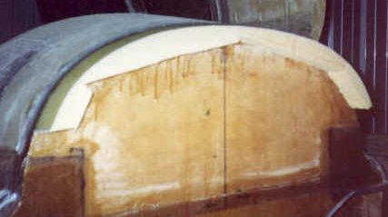
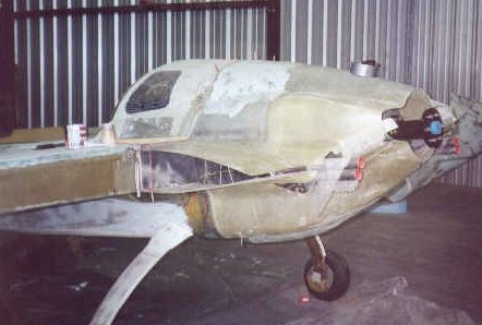
The cowl is fitted to the firewall by a lip that is built up using foam blocks and laying a BID "lip" around the perimeter of the firewall. After cure the foam is removed to leave only the BID lip. I'll wait to actually mount the cowling until the engine arrives. That way it will be straight and even around the prop opening. Here is a picture:
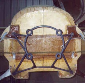
I ordered an engine mount from Jeff Russell - a powder coated, H-framed unit with a 1" lower thrust line built by RANS. I received the mount and installed it in about 30 minutes after carefully leveling the fuselage and drilling out the hardpoints. The mounting bolts from the plans are too long due to AeroCad's frame having a smaller mount attach tube, so I had to go to the airport FBO to get the right size. I also had to grind away a little of the diameter of the 2 lower large washers so that they would fit on the forward side of the firewall. After all the fidgeting, here is the mount temporarily mounted to the firewall.
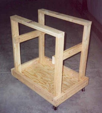
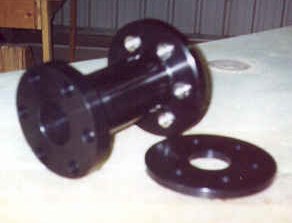
I took the time to build the engine stand that the plans show (costs about $45 to build - a whole lot cheaper than a hoist!). It is 1 inch lower to accommodate the lower thrust line, but other than that it is per the plans. Good and stout! I also ordered and received (in record time) a 8 inch prop extension with a 7 inch diameter prop flange and crush plate from Sabre Manufacturing. Here are pictures of both.
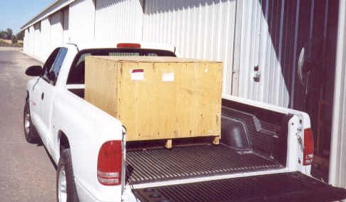
The big day arrived on October 20 when I went to the trucking depot in Chandler to load the engine (in a big 'ol crate) into my pickup. Pardon my excitement, but to me this was one of the biggest events in this whole adventure. I was finally taking delivery of the powerplant for this plane I have been building for just over four years! The good folks at the depot loaded the crate into the back of my truck and off I went to the hangar to get it unloaded. When I arrived, I couldn't help but take a picture.
Well, now is when the fun began! I tore the crate apart and there sat the prettiest looking engine I had ever seen! AeroSport Power had done a terrific job - this thing looked brand new! But then it occurred to me that I had no way of getting the engine off the crate and onto my engine cart. I took a drive down the row of hangars and found a couple of guys working on a biplane that looked like they had a bunch of tools. Sure enough, they had an engine hoist and offered to bring it to my hangar to help me unload the engine. After about 20 minutes the job was done and the engine was sitting on the cart.
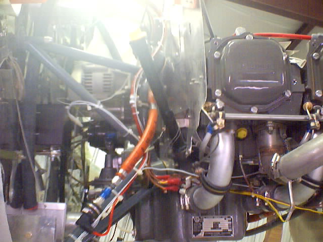
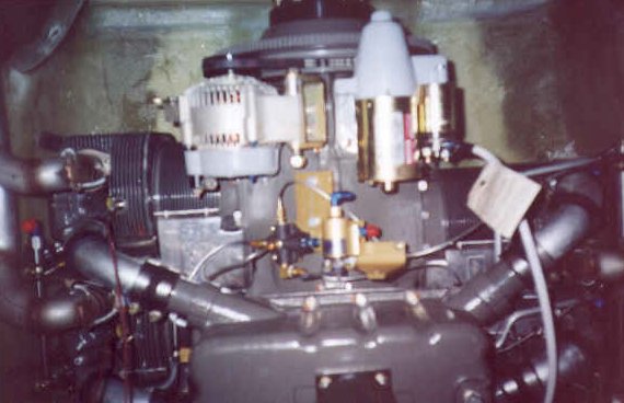
If you are like me, I was very curious what an aircraft engine looked like up close but never have been able to see one that wasn't covered by an engine cowling or something. I took the liberty of taking a couple of pictures of the engine from different angles as it sat on the crate so others could see what I am dealing with. Here they are:
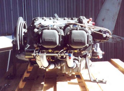
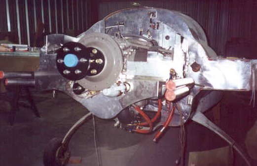
This is a view from the left side. The Skytech starter and ring gear are to the left in the picture and the left magneto can be seen on the right side of the picture with the fuel pump directly below it. The next picture shows more detail of the firewall side of the engine.
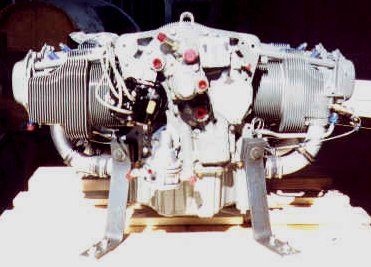
The sun was shining bright on this shot, so the contrast is not real good, but the magneto is the black part with the four cables coming out of it just to the right of the cylinder on the left side of the picture. Below it and to the right is the fuel pump. The Airflow Performance fuel injection air intake will be mounted directly underneath the engine facing the firewall. One of the brass colored fuel injectors can be seen to the right of the right cylinder. The blue colored pegs sticking out at an angle from the top of the cylinders are the spark plugs driven by the magneto. The blue color is just a protective plastic cover put there for shipment. The Light Speed Engineering electronic ignition will drive the other four plugs which will be mounted into the lower side of the cylinders. The hook at the top center of the engine is the lift point when using a hoist. The metal brackets holding the engine off the crate are actually mounted to the two lower engine mount holes.
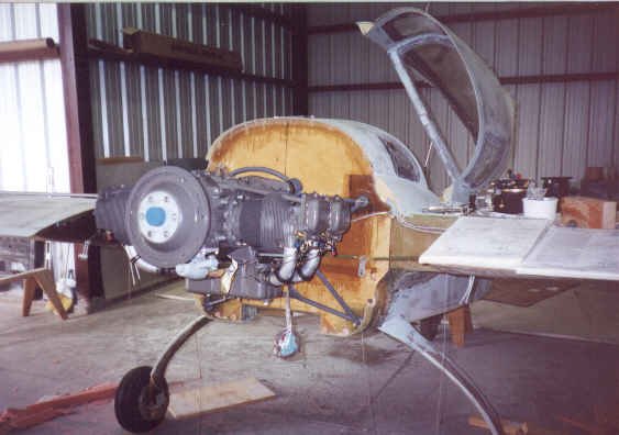
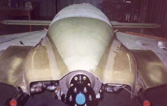
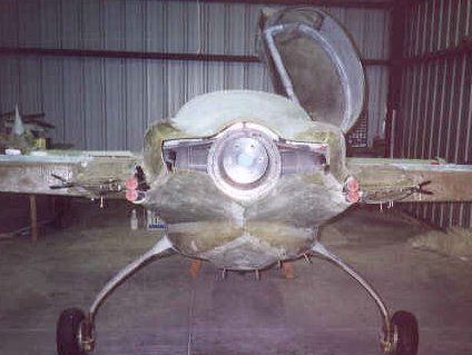
I bolted the engine mount and bushings to the engine and tightened them to the required torque then swung the cart around so that the holes in the firewall lined up with the mount. I lined up one of the top firewall mounting bolts to the engine mount frame by shimming a wheel up a bit, but it slid on with little effort. I then did the other top bolt in a similar way. The bottom two bolts were easy after that. I tightened the nuts and pulled the cart away and stood back to get a look. Wow - another major milestone complete! Here is the picture from the rear of the plane with the engine mounted.
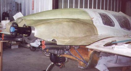
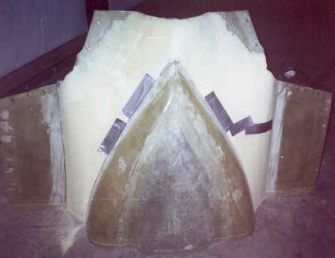
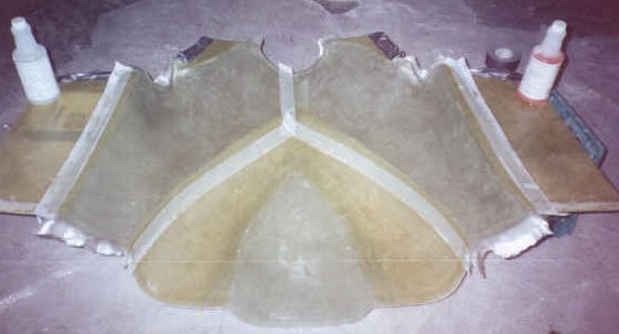
Now the plumbing begins! I knew I needed to make some mods to the lower cowling due to the fuel injection unit and the related fuel filter and pump that came with the fuel injector are different than those called for in the plans. The upper cowl also needed modification since I raised the height of the firewall . I started with the upper cowling. I attached it to the strake flanges so that the part of the cowl that fits to the wings was in the proper location. After taping the exposed firewall and flanges with duct tape, I poured pour foam on top of the cowl where it needed to be raised in height up to the curvature of the fuselage. When this cured (about 30 minutes) I sanded the foam to get a nice even curvature blending it in to the existing cowl and fuselage contour. I then removed the cowl with foam attached and laid up three plies of BID over the foam overlapping the cowl. After cure, I flipped the cowl upside down and cut away the part of the original cowl that was under the foam. I then removed all the foam and cleaned up the fiberglass surface so I could lay up an additional 3 plies of glass from the inside. In a second step, I performed this same type of surgery to the sides of the cowl that wrap around the cylinders. Presto - a new upper cowl!
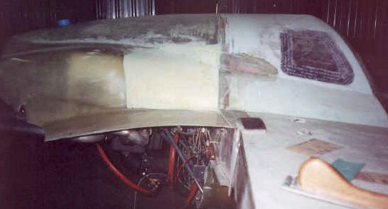
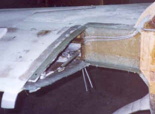
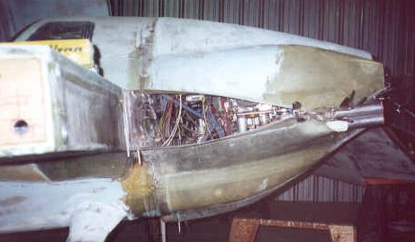
The bottom cowl interfered with my fuel injection unit in the scoop area, so I fabricated a new scoop in a similar fashion to the upper cowl by using pour foam and 3 plies of BID inside and out to create the new shape. The scoop now sits 1 inch lower than the original cowl did making the scoop opening larger. I am an optimist, so I am counting on the extra air to aid in cooling without creating too much of a drag penalty. Here you can see the new scoop area as I was building the lip of the scoop onto the fuselage bottom. It was shaped from foam then glassed to match the cowl. The cutouts on the left and right of the scoop area were required to clear the exhaust pipes - again another patch job due to lowering the engine 1"!
The cowls are attached around the fuselage and along the wings with Phillips head screws and nutplates - total of 15 fitting for the top cowl and 16 along the bottom. The flanges had to be built on the wings and spar to accommodate this and must be done with the wings on.
I then removed the wings and completed the aft joint where the two cowl pieces attach.
At this point I decided to complete Chapter 15 which involves attaching the firewall insulation and aluminum liner as well as the fuel filter and fuel boost pump on the firewall.
After completing Chapter 15 on Dec 4, 1999, I began to work on the engine baffling. Templates for these pieces are included in the plans and are cut from 6061 aluminum sheet. I made temporary paper templates to check size before cutting the metal. After ensuring the templates fit, I used a combination of tin snips and a band saw to cut the metal and a small tin bender to make the required bends in the baffles.
Instead of going into all the details of each baffle, let's just say that the intent is to make a tight fitting liner around the fins of the engine so that the cooling air goes where it needs to and cools the engine. I made my baffles oversize on top to compensate for the taller cowl and made similar adjustments for the bottom pieces.
After making all the modifications to the upper and lower cowls they became too heavy, in my opinion, to use on the plane! So, I decided to make molds from them. With the molds I will be able to make duplicates of these cowls in one piece that will be much lighter and tailored for my plane. Once I decided to make these parts the plugs, I no longer cared what I used for filler so I began to use regular body filler (Bondo). After getting the parts flared into the fuselage sides and contoured to my liking, I used a spray primer from the auto store to paint the cowls. I wet sanded these down to 330 grit and then painted them.
After the mold plugs were painted, I waxed them real good with regular car wax and then sprayed on Partall mold release. This is a green liquid that is water soluble and dries to a very thin film. Its function is to keep the mold from being permanently attached to the plug! After the Partall dried I sprayed in a thick coating of tooling gelcoat. This is a two part polyester material that will become the inside surface of the mold. It is durable and can be repaired if necessary. While I only intend to make one part from these molds, the gelcoat makes a good surface to lay up cloth against over and over again. After that was sprayed in I immediately began laying up 5 layers of chopped strand fiberglass mat with Polyester resin. This is a completely different type of resin than the plane is built from and dries very quickly. It also doesn't have to be sanded between layers if you let it cure completely. In fact, I only laid up the first two layers and let that cure overnight. I came back the next day and completed the last three layers. I waited about 5 days for the molds to completely cure before I popped them loose from the plugs. The top cowl came loose fairly easily, but the bottom cowl was more of a struggle due to the stiffer shape of the cowl. They both turned out very nice in my opinion for my first molds! I had to do some slight repairs in a couple of spots, but it was easily done.
OK, so I've wasted plenty of time getting to this point, so I better get finished. I waxed the new molds, sprayed in the Partall and laid up three plies of cloth, BID - UNI - BID over the whole mold surface followed by an additional three BID layers around all the edges to stiffen them. This was using epoxy just like the rest of the plane. After a week I pulled the parts loose from the molds and admired my work! They turned out GREAT! So much lighter that the ones I had started with and the fit to the fuselage is perfect.
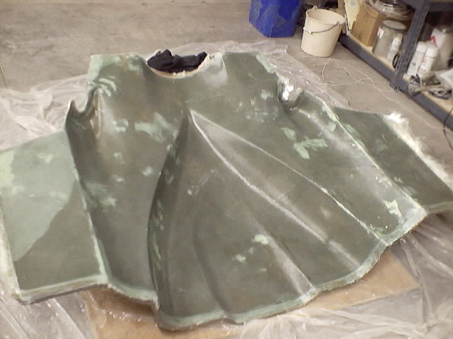
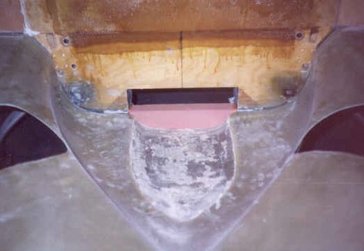
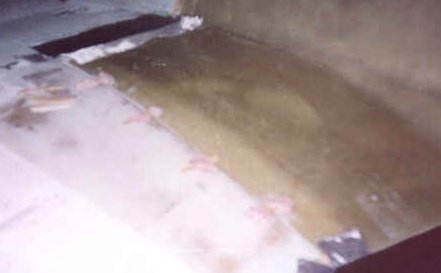
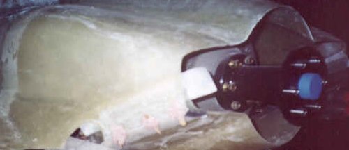
This is the bottom cowl mold with the fiberglass laid in.
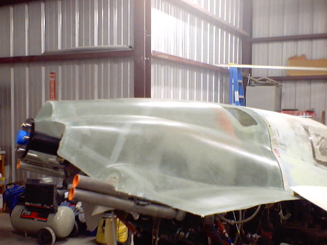
Here is the final product (top cowl) straight out of the mold.
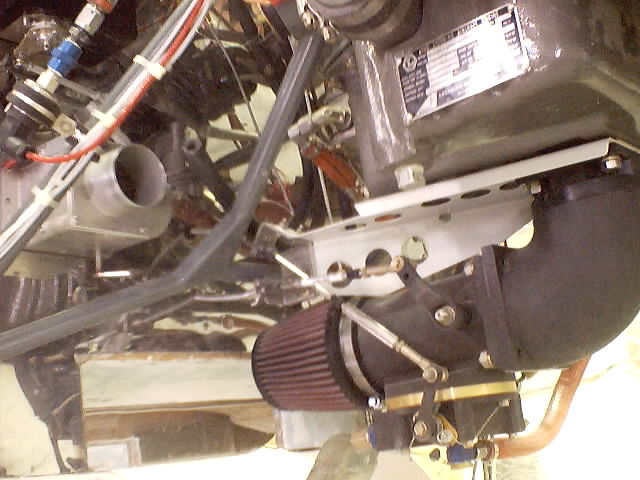
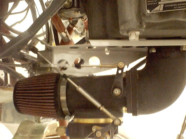
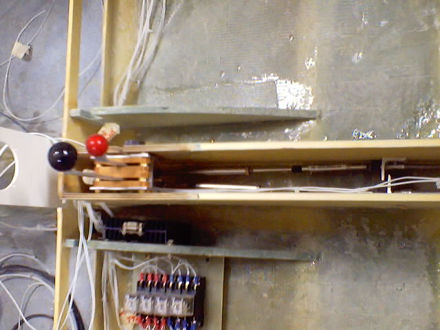
I needed to run mixture and throttle cables to the fuel injector controller and purchased these through Aircraft Spruce. They are identical and are 84" long. I replaced the Brock throttle quadrant after deciding to use a Van's Aircraft RV-6? quadrant instead.. I had to also build some custom cable clamps that attached to the inside of the center console to hold the new cables in place as well as a bracket from Van's Aircraft to hold the cables in place at the business end. I then installed short adapters to extend the cable ends to the exact length needed to reach the throttle and mixture control arms on the fuel injector. Here are a few shots of the fuel injection controller, cables and bracket (first picture), the new throttle quadrant and cable area in the cockpit (second picture) and a view from the bottom of the engine looking up at the distribution spider (third picture). Also shown in the second photo is the Skytech starter and B&C 60A alternator.
The fuel tank selector handle and cabin heat control are located between the front seat passengers just below the map pocket. Here's a photo of that after the plane was completed and labels were attached. LEFT tank is top, RIGHT tank is to the right in this picture. Left and below are both OFF. The handle in this picture is showing the full selector in the OFF position.

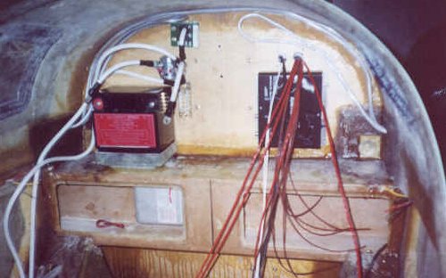
After my Vision Microsystems VM1000 engine monitor arrived in mid-March, 2000 I began wiring all the transducers to the engine. The VM1000 monitors all critical engine functions as well as the electrical system voltage and amperage. Each function is monitored by some sort of sensor that is wired to a central processing unit mounted on the cabin side of the firewall. This CPU converts all the sensors' signals into data that can be displayed on the main display screen on the instrument panel via a long ribbon cable that connects the two. The photo below shows where the sensor wires enter the cabin (red wires) directly above the fuel injection computer. The Hall Effect sensor can be seen above the battery contactor with the cable going through it. This measures the current being used by the electrical system and will be displayed on the VM1000. The VM1000 computer will be mounted in the space between the battery and the fuel injection computer. Crowded, isn't it!
If all of that wasn't enough, I hated the look of the aluminum firewall and replaced it with stainless steel since I had all the cowls and engine off for so long. Not a big deal - it took about two days to do it all using the old firewall liner as a template. The stainless is sure a lot shinier! Wires in the engine compartment are all bundled and secured!